- Original Article
- Published:
Composite Configuration Interventional Therapy Robot for the Microwave Ablation of Liver Tumors
Chinese Journal of Mechanical Engineering volume 30, pages 1416–1425 (2017)
Abstract
The existing interventional therapy robots for the microwave ablation of liver tumors have a poor clinical applicability with a large volume, low positioning speed and complex automatic navigation control. To solve above problems, a composite configuration interventional therapy robot with passive and active joints is developed. The design of composite configuration reduces the size of the robot under the premise of a wide range of movement, and the robot with composite configuration can realizes rapid positioning with operation safety. The cumulative error of positioning is eliminated and the control complexity is reduced by decoupling active parts. The navigation algorithms for the robot are proposed based on solution of the inverse kinematics and geometric analysis. A simulation clinical test method is designed for the robot, and the functions of the robot and the navigation algorithms are verified by the test method. The mean error of navigation is 1.488 mm and the maximum error is 2.056 mm, and the positioning time for the ablation needle is in 10 s. The experimental results show that the designed robot can meet the clinical requirements for the microwave ablation of liver tumors. The composite configuration is proposed in development of the interventional therapy robot for the microwave ablation of liver tumors, which provides a new idea for the structural design of medical robots.
1 Introduction
Microwave ablation of liver tumors refers to the inactivation of liver tumors in situ under image guidance by heating the liver tumor tissue via microwave to a high temperature (above 60 °C), achieving an effect of complete coagulation necrosis of the tumor. Microwave ablation has developed rapidly and become an important method for tumor therapy.
The application of a medical robot system in tumor thermal ablation therapy can improve the precision of ablation and ability of conformal ablation as well as reduce the dependence of the therapy on the experience of physicians [1,2,3,4].
Hong, et al [5] designed an automatic needle insertion robot system based on ultrasonic image guidance. The ultrasonic probe and the puncture needle were arranged on the same plane, and then the real time ultrasonic image was used to track the target point. The robot was control to push the needle. However, the system could only achieve two-dimensional positioning in the ultrasonic image plane, and it could not complete the active positioning in the real sense.
Researchers in Johns Hopkins University developed a set of dual-arm robot that was used for ultrasound-guided radiofrequency treatment. One arm was mounted to an ultrasonic probe, and the other one controlled the puncture location [6]. The system was a completely open navigation system, which was suitable the operation of anatomic tissue exposure.
The Steady Hand [7] minimally invasive surgery robot system for eyes was developed by Johns Hopkins University in the USA, which could assist in eye surgery. The robot had a small volume, but its working space was very small too.
Chinese PLA General Hospital and Beijing Institute of Petrochemical Technology developed a surgical-assistant robot for the microwave ablation of liver tumors [8,9,10]. The robot could only realize the support function of microwave needle, which had no navigation function.
Xu, et al [11,12,13], Yang, et al [14], Ni, et al [15], and Xiong, et al [16] proposed a microwave ablation treatment for malignant liver tumors using a three-dimensional ultrasound-guided robot assisted system. The robot system was composed of an imaging module, a puncture robot, a microwave ablation thermal field simulation module and a surgical navigation software. The test results showed that the localization accuracy of the robot was within the 3-mm minimum, and the highest one was (1.6 + 1.0) mm. The average relative error between the volume and simulation results was 5.6%. Although the positioning accuracy can meet the clinical requirements, the robot adopted the SCARA configuration and the body was huge. In order to ensure safety, the movement speed was very slow. The robot was difficult to integrate into the operation process.
In addition to the robots for the microwave ablation, some research teams did some basic research such as the evaluation system, preoperative planning, image processing and needle steering for a robot.
The role of navigation and robot technology in the treatment of tumor thermal ablation under the ultrasound guidance was evaluated by Lu, et al [17,18,19]. Nouaille, et al [20] deal with the design process adapted to medical robots.
Gao, et al [21] presented a survey of the state of the art of research on algorithms of needle steering techniques, the surgical robots and devices. Guiatni, et al [22], Wang, et al [23] and Gulhar, et al [24] proposed medical imaging systems to guide robots. The planning system was presented by Azimian, et al [25] and Weede, et al [26]. Yang, et al [27] developed a novel surgery robot for feeding guide wire and gave a risk criterion for the system.
Spanish researchers at Malage Victor F. Munoz University developed an ERM robotic system to assist minimally invasive surgeries. The robot had 5 DOFs, including 3 active DOFs for the laparoscopic camera position control and 2 passive DOFs for the wrist structure [28]. Fu, et al [29] at Harbin Institute of Technology designed a laparoscopic robot whose structure was similar to the former. Although the two robots were realized by combination of the active and passive joints, these were not suitable for ultrasound-guided microwave ablation and the control systems were complex for clinical therapy.
Deng [30] proposed a navigation algorithm for tumor ablation robots that was based on a universal robot (UR5). The robot was not limited to ultrasound imaging and microwave tumor ablation surgery. Since the industrial robots were adopted, the control system could not be developed according to the requirements of the operation.
In conclusion, only active joints are adopted generally for the existing interventional therapy robots. The robots can complete the basic positioning function with poor clinical applicability, since their sizes increase rapidly with the positioning range, and the positioning speed is slow with complex control of automatic navigation considering safety factors. Although some robots for laparoscopic surgery are designed with active and passive joints, they are not applicable to the microwave ablation of tumors. Because the surgical tools for laparoscopic surgery are different from those for microwave ablation surgery and their navigation principles were different also.
Therefore, this paper presents a composite configuration interventional therapy robot system for the microwave ablation of liver tumors that can complete intelligent positioning and navigation of surgical instruments under ultrasound guidance and the robot can be pulled in or retreated from operation rapidly to expand its working space. The robot can be well integrated into the clinical operation.
2 Composite Configuration Robot Structure
As shown in Fig. 1, the robot is composed of a Cartesian worktable, telescopic arm and hand manipulator.

Composite configuration robot
-
(1)
The Cartesian worktable is locked at the rear of the surgical bed. The Cartesian worktable can accurately adjust the position of the ablation needle tip with an absolute positioning accuracy of 8 μm. Its motion ranges in the X, Y and Z directions are 200, 50 and 50 mm respectively.
-
(2)
The telescopic arm has 7 DOFs (two ball joints and one elbow joint) without a driving motor and has a large movement space. Its motion ranges are 500 mm in the length direction, 1000 mm in the width direction and 400 mm in the height direction. It can realize rapid positioning in 10 s and can lock all joints simultaneously by its locking device, as depicted in Fig. 2.
Fig. 2 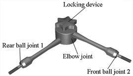
Telescopic arm
-
(3)
As shown in Fig. 3, the hand manipulator has two DOFs and is driven by two DC servo motors. It can clamp an ablation needle and keep the motion center of the needle tip in the same puncture point while adjusting its posture. This type of hand manipulator is known as remote center of motion (RCM).
Fig. 3 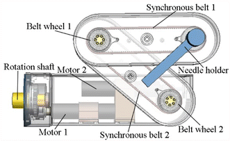
RCM type of hand manipulator


In the ablation operation, the ultrasound image navigation control system can automatically operate the RCM mechanism according to the location of the tumor, and the ablation needle in the RCM can be adjusted to the appropriate puncture path.
3 Kinematics of the Robot
3.1 Simplified Robot Navigation Mechanism
The Denavit-Hartenberg(D-H) method was adopted to establish the mechanism diagram of the robot, as shown in Fig. 4. The D-H parameters of each joint are shown in Table 1.

Robot mechanism diagram
The parameter values in Table 1 are the measured values of the arm D-H parameters, and the joint variables are set as an initial value.
The homogeneous transformation matrix between the joints can be obtained from the table.
In Eq. (1), i = 1 to 12, so
In the robot operation procedure, the robot navigation motion can be performed by its Cartesian worktable and RCM mechanism only after its telescopic arm is drawn to the planned position and locked. In this case, the telescopic arm is supposed to be a rigid body, and the schematic of the robot mechanism can be simplified. The simplified robot navigation mechanism has five degrees of freedom (Z 1, Z 2, Z 3, Z 11 and Z 12). Therefore, the homogeneous transformation matrix is
In Eq. (4), the rotation matrix is represented by M and the translation matrix is represented by P.
The above equation indicates that P is related to only the parameter d 1, d 2 and d 3, and then M is related to only the parameter θ 4 and θ 5; thus, the robot is completely decoupled when the robot telescopic arm is locked.
3.2 Inverse Kinematics Analysis
According to the clinical operations, the 7 DOFs of the telescopic arm can be simplified as follows:
-
(1)
The rear ball joint is simplified as a ball sliding joint, i.e., θ 4 remains unchanged—because its rotation around the body length direction can be achieved by θ 11 instead of θ 4, as shown in Fig. 4.
-
(2)
The front ball joint is simplified as a 0-DOF joint, i.e., θ 8, θ 9 and θ 10 remain unchanged—because its rotation axis is extremely short (approximately 5 mm), and the rotations of θ 8, θ 9 and θ 10 are very small (approximately 15°), which has only a slight influence on the position accuracy of the telescopic arm.
Figure 5 shows the simplified mechanism diagram of the telescopic arm; then, Eq. (3) can be rewritten as

Simplified mechanism diagram of telescopic arm
In Eq. (5), W is the rotation matrix and N is the translation matrix.
Letting N = \(\left( {\begin{array}{*{20}c} {k_{1} } & {k_{2} } & {k_{3} } \\ \end{array} } \right)\)’, k 1, k 2 and k 3 are the three coordinates of the RCM tip and should equal to the planned coordinates of the puncture point.
Next, the following equations are set:
The values of θ 5, θ 6 and θ 7 can be obtained by Matlab2016a, and the theoretical value of the position and posture of the telescopic arm can be represented.
4 Robot Navigation
4.1 Procedure of the Robot Navigation
Robot navigation was developed from manual navigation in the clinical operation. The current microwave ablation clinical procedure is as follows:
-
(1)
Scanning with the B-Mode ultrasonic probe
After scanning the patient’s liver tumors by FreeHand (free arm scanning), the image information is input to the surgical planning software in computer.
-
(2)
Making the three-dimensional reconstruction
The physician completes the three-dimensional reconstruction of the important peripheral vascular tumors to establish a preoperative 3D model coordinate system.
-
(3)
Planning the ablation needle path
According to the target location and 3D model of important peripheral vascular tumors the physician performs ablation needle path planning in the ultrasonic image navigation workstation.
-
(4)
Making the incision
According to the surgical planning results, the physician makes an incision at the puncture point.
-
(5)
Pushing the ablation needle
The patient holds his breath for a moment, and the doctor physician pushes the ablation needle into the tumor. The entire process lasts for 5–10 s.
-
(6)
Evaluating the operation
After the operation, the patient will be scanned again to evaluate the effect of the operation.
Based on the above manual navigation. The main procedures of the robot navigation are as follows:
-
(1)
Calculating the coordinates of the centroid of the tumor’s 3D model by the self-developed navigation software and considering them to be the coordinates of the target point;
-
(2)
Obtaining the puncture point O based on the physician’s planning surgical path RM on the interface of the navigation software;
-
(3)
Mapping all the above point coordinates to the robot coordinate system;
-
(4)
Positioning the telescopic arm;
-
(5)
Adjusting the Cartesian worktable localization and RCM localization.
4.2 Telescopic arm intelligent localization
As noted above, the telescopic arm will be posed and locked according to the surgical planning situation at the beginning of the robot navigation. The intelligent positioning of the telescopic arm is achieved as follows:
-
(1)
Obtaining the values of θ 5, θ 6 and θ 7 by the inverse kinematics Eq. (6);
-
(2)
Sending the above solutions into the arm positioning graphic display interfaces, as shown in Fig. 6(a);
Fig. 6 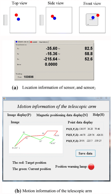
Graphic display interfaces of the telescopic arm
-
(3)
Detecting the position of the telescopic arm by four NDI micro sensors, as shown in Fig. 7;
Fig. 7 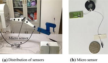
Attachment of the magnetic locator sensors
-
4)
Drawing the arm to reach the planning position until the red alarm light of Fig. 6(b) is on.


4.3 Cartesian Worktable Localization
After the telescopic arm is localized, the further precise positioning of the needle tip is fulfilled by the Cartesian worktable.
According to Eq. (4), the position of the robot RCM mechanism is controlled by Cartesian worktable, i.e., its positioning motions in the X, Y and Z directions have a decoupling relationship, as shown in Fig. 8.

Moving direction of Cartesian worktable
The adjusting values in each direction can be calculated according to Eq. (7).
In Eq. (7), \(X_{{w_{1} }} , Y_{{w_{1} }} {\text{and }}Z_{{w_{1} }}\) are the coordinate of the puncture point and \(X_{{w_{0} }} , Y_{{w_{0} }} {\text{and }}Z_{{w_{0} }}\) are the coordinates of the current coordinates of the needle tip point.
4.4 RCM Localization
After telescopic arm intelligent localization and Cartesian worktable localization, the position of the needle tip is determined.
The needle’s posture is adjusted by RCM. The RCM localization algorithm is used to adjust the posture of the ablation needle according to the target point and surgical planning results. This adjustment can assist physicians to avoid the important blood vessels and tissues in hepatic tumor ablation surgery. The elevation view of the pose of the ablation needle is shown in Fig. 9.

Elevation view of the pose of the needle
According to Eq. (4), the posture of the needle is controlled by RCM. In the RCM mechanism, RCM’s rotation and swing movements are independent, as shown in Fig. 10.

Schematic diagram of the posture adjustment
In Fig. 10, the solid line OR 0 is the current posture of the needle. The dotted line OR is an extension line of MO. The three points (R, O and M) must be in a straight line to assist doctors in avoiding the important blood vessels and tissues during hepatic tumor ablation surgery.
Angle θ is a space angle from the current posture to a reasonable posture. To obtain the space angle, two DC servo motors must turn corresponding angle α and β.
The algorithm of the rotation angle α and the swing angle β are as follows:
4.5 Example of Robot Navigation
To illustrate the robot navigation process more clearly, an example is shown below.
-
(1)
After Scanning with the B-Mode ultrasonic probe and the three-dimensional reconstruction of tumor imaging, the coordinates of the target point (tumor centroid) M in Fig. 11 are obtained as (53.271, 46.466, −125.244).
Fig. 11 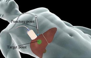
Example of robot navigation
-
(2)
Through the surgical planning, the coordinate of puncture point O is determined as (−61.369, 111.089, −141.497).
-
(3)
Letting (k 1, k 2, k 3) = (−61.369, 111.089, −141.497), it can be obtained that θ 5 = 51.7°, θ 6 = 39.7° and θ 7 = −86.1° using Eq. (6).
-
(4)
Draw the arm to reach the planning position until the indicator on the area D of Fig. 7 is lit.
-
(5)
Using the needle tip magnetic senor, the current coordinates of the needle tip point (O’) are measured to be (−59.254, 108.375, −139.473).
-
(6)
Calculate the coordinate difference between O and O’.
-
(7)
Using Eq. (7), the controllable variables of the Cartesian worktable are calculated to be \(\Delta X_{w}\) = −2.115, \(\Delta Y_{w}\) = 2.714, and \(\Delta Z_{w}\) = −2.024.
-
(8)
Using the magnetic senor, the coordinates of the center of the RCM’s axis (P) are determined to be (−191.355, 97.754, −396.778).
-
(9)
Using Eq. (8), the controllable variables of RCM are calculated as α = 15.36° and β = 23.73°.
-
(10)
Control the Cartesian worktable and RCM to make the ablation needle reach the planning position and gesture by the self-developed navigation software.

5 Force Feedback Experiments
A simulation method has been designed to imitate the clinic interventional therapy of the robot. The steps of the method are as follows:
-
(1)
In the laboratory environment, doctors used the ultrasonic probe with NDI micro sensor to scan the liver of the experimental person and used self-developed navigation software for liver image acquisition, as shown in Fig. 12;
Fig. 12 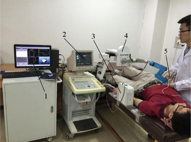
Simulation experimental. 1 Ultrasonic image navigation workstation; 2 B-mode ultrasonography system; 3 Magnetic orientation system; 4 Composite configuration robot; 5 Ultrasonic probe with NDI micro sensor
-
(2)
A virtual circle was built by acquisition multiple normal liver ultrasound images, and the circular three-dimensional model was reconstructed to simulate the liver tumor, as shown in Fig. 13;
Fig. 13 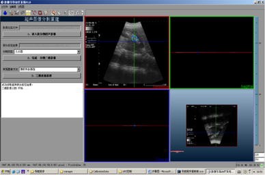
Liver tumor segmentation map navigation software
-
(3)
The physician drew the arm to reach the planning position, and the indicator light in Fig. 7 was lit;
-
(4)
The self-developed navigation software was used to adjust the position and posture of robot hand manipulator until the ablation needle tip reaching the puncture point determined by the image of the navigation system, as shown in Fig. 14;
Fig. 14 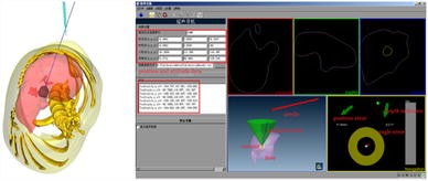
Real-time locations of the actual needle and virtual liver tumor before robot navigation
-
(5)
Only after the experimental person left, the physician push the ablation needle tip into the virtual tumor target displayed in the navigating interface and record the coordinate localization data of the ablation needle tip and top in different position, as shown in Fig. 15.
Fig. 15 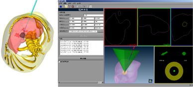
Ablation needle tip pierced into the virtual liver tumor after navigation and posture adjustment


Descriptions of the illustrations in Figs. 14 and 15 are provided below:
-
(1)
The lower right part of the figures is the three-dimensional display of the actual ablation needle, navigation lines and the liver with a virtual tumor.
-
(2)
The lower right part of the figures is the 2D parametric picture of the actual ablation needle position and the navigation line diagram, where the white “+” signal indicates the target position.
-
(3)
The red “+” signal indicates the position of the actual ablation needle tip and the green ball signal indicates the posture of the ablation needle, i.e., only when the above three signals are overlapping is the actual ablation needle tip into the target.
-
(4)
There are two groups of arrows and data to indicate the deviation direction and data and a gray bar to indicate the depth of ablation needle.
Ten individuals were tested using the above simulation method, and the data are provided in Tables 2 and 3.
As shown in Fig. 16, the needle tip magnetic sensor and needle top magnetic senor can measure the real-time coordinate of the needle tip and needle top.

Ablation needle
Table 2 provides the navigation process data of test No. 1, and its puncture point and target positions are (−61.3694, 111.089, −141.497) and (53.2712, 46.4661, −125.244), respectively.
Table 3 provides the navigation error data of ten tests. The mean navigation error is 1.488 mm, and the maximum error is 2.056 mm, which met the clinical requirement of a 5-mm maximum error.
The 14G (diameter: 2.15 mm) ablation needle was adopted in these experiments. The needle was made from 304 stainless steel, and its tip was ceramic. These characteristics can reduce the deformation of the needle in the inserting procedure. The maximum deformation did not exceed 1 mm.
6 Conclusions
-
(1)
An interventional therapy robot with composite configuration is developed, and combination of active and passive joints reduces the size of the robot with a wide range of movement. Rapid positioning for the ablation needle is realized with operational safety, and the positioning time is in 10 s. In addition, the cumulative error of positioning is eliminated and the control complexity is reduced by decoupling active parts.
-
(2)
The navigation algorithms of the robot are proposed corresponding with composite configuration and it is verified with the simulation clinical test method. The mean error of navigation is 1.488 mm and the maximum error is 2.056 mm, both of which meet the clinical requirements for positioning accuracy.
-
(3)
The robot system can move flexibly in large motion range with higher positioning accuracy, its structural design provides a new idea for the development of medical robots.
References
Zhu-Huang Zhou, Qi-Ying Ding, Lei Sheng, et al. Advances in noninvasive monitoring of thermal therapy with ultrasound elasticity imaging. Beijing Biomedical Engineering, 2013, 32(6): 641–646. (in Chinese)
Zhu-Huang Zhou, Wei-Wei Wu, et al. Advances in image navigation techniques for tumor thermal ablation. Beijing Biomedical Engineering, 2014, 33(4): 415–419. (in Chinese)
Zhu-Huang Zhou, Wei-Wei Wu, Shui-Cai Wu, et al. Recent advances in noninvasive ultrasound monitoring of thermal therapy for tumors. Science & Technology Review, 2014, 32(20): 19–24.
Wei-Wei Wu, Zhu-Huang Zhou, Shui-Cai Wu, et al. A survey of intraoperative image registration approaches to ultrasound guided interventional therapy. Beijing Biomedical Engineering, 2015, 34(6): 639–645. (in Chinese)
J Hong, T Dohi, M Hashizume, et al. An ultrasound-driven needle-insertion robot for percutaneous cholecystectomy. Physics in Medicine and Biology, 2004, 49(3): 441–455.
E M Boctor, G Fischer, M A Choti, et al. A dual-armed robotic system for intraoperative ultrasound guided hepatic ablative therapy//Proceedings of the 2004 IEEE International Conference on Robotics & Automation, Piscataway, NJ, USA, April 26–May 1, 2004, 3(26): 2517–2522.
R Taylor, P Jensen, L Whitcomb. A steady-hand robotic system for microsurgical augmentation. International Journal of Robotics Research, 1999, 18(12): 1201–1210.
Ying-Yu Cao, Shuang-Cheng Deng, Wei-Tao Cui, et al. A study of ultrasound-guided robot system for liver cancer coagulation therapy. Journal of Beijing Institute of Petro-chemiaclal Technology, 2012, 20(4): 1–6. (in Chinese)
Shuang-Cheng Deng, Li-Pei Jiang, Ying-Yu Cao, et al. A needle-holding robot for ultrasound guided percutaneous hepatic microwave ablation and initial experiments. The 1st Conference on Intelligent Robotics and Applications, Wuhan, China, October 15–17, 2008: 1173–1182.
Ying-Yu Cao, Bo-Jin Qi, Shao-Xian Wang, et al. The navigation and positioning method of active plus passive ultrasound-guided robot for liver cancer coagulation therapy. Advanced Materials Research, 2013, 17(8): 1453–1459.
Jing Xu, Zheng-Zhong Jia, Zhang-Jun Song, et al. The robotic system of microwave coagulation therapy for liver cancer based on ultrasound navigation. Robot, 2007, 29(5): 456–462. (in Chinese)
Jing Xu, Ken Chen, Xiang-Dong Yang, et al. Intra-operation 3D ultrasound navigation system in intervention therapy for liver cancer. Chinese Journal of Biomedical Engineering, 2007, 26(5): 719–723.
Jing Xu, Xiang-Dong Yang, Sen-Qiang Hu, et al. Three-dimensional ultrasound image-guided robotic system for accurate microwave coagulation of malignant liver tumors. International Journal of Medical Robotics & Computer Assisted Surgery, 2010, 6(3): 256–268.
Xiang-Dong Yang, Jing Xu, Shao-Li Liu, et al. On error propagation of the ultrasound guided robot for liver cancer coagulation therapy. Robot, 2008, 30(5): 440–446. (in Chinese)
Xiao-Xia Ni, Xiao-Ling Yu, Yang Wang, et al. A study of ultrasound-guided percutaneous microwave ablation of adrenal tumor. Chinese Journal of Medical Imaging, 2011, 19(3): 185–189.
Min Xiong, Ken Chen, Xiang-Dong Yang, et al. Intervention robot system THMR-I and its clinical application. High Technology Letters, 2009, 19(12): 1281–1287.
Tong Lu, Ping Liang, Zhi-Gang Cheng. Effects of navigation and robot technology on percutaneous ultrasound-guided liver tumor ablation: accuracy and feasibility of clinical application. Journal of Clinical Rehabilitative Tissue Engineering Research, 2010, 14(4): 625–628.
Tong Lu, Jing Xu, Ping Liang, et al. A robot system for US-guided microwave ablation therapy(a pilot study). China Medical Devices Information, 2007, 13(3): 5–8.
Tong Lu, Ping Liang, Shuang-Cheng Deng, et al. A robot for image-guided percutaneous intervention: decoupled motion capability correlated to the positioning and orientation steps of the percutaneous intervention. Journal of Clinical Rehabilitative Tissue Engineering Research, 2009, 13(48): 9447–9450.
L Nouaille, M A Laribi, C A Nelson, et al. Design process for robotic medical tool guidance manipulators. Proceedings of the Institution of Mechanical Engineers Part C: Journal of Mechanical Engineering Science, 2015, 230(2): 259–275.
De-Dong Gao, Yong Lei, Hao-Jun Zheng. Needle steering for robot-assisted insertion into soft tissue:a survey. Chinese Journal of Mechanical Engineering, 2012, 25(4): 629–638.
M Giuatni, V Riboulet, C Duriez, et al. A combined force and thermal feedback interface for minimally invasive procedures simulation. IEEE/ASME Transactions on Mechatronics, 2013, 18(3): 1170–1181.
Li-Jing Wang, Xue-Li He, Hong-Peng Li. Development of a percentile based three-dimensional model of the buttocks in computer system. Chinese Journal of Mechanical Engineering, 2016, 29(3): 633–640.
A Gulhar, D Briese, P W Mewes, et al. Registration of a robotic system to a medical imaging system. IEEE/RSJ International Conference on Intelligent Robots and Systems, Magdeburg, Germany, September 28–October 2, 2015: 3208–3213.
H Aaimian, M D Naish, B Kiaii, et al. A chance-constrained programming approach to preoperative planning of robotic cardiac surgery under task-level uncertainty. IEEE Journal of Biomedical & Health Informatics, 2015, 19(2): 612–622.
O Weede. Knowledge-based system for port placement and robot setup optimization in minimally invasive surgery..IFAC Proceedings Volumes, 2012, 45(22): 722–728.
Xue Yang, Hong-Bo Wang, Li Su, et al. Operation and force analysis of the guide wire in a minimally invasive vascular interventional surgery robot system. Chinese Journal of Mechanical Engineering, 2015, 28(2): 249–257.
V F Munoz, J Fernandez-Dez-Lozano, J Gomez-De-Gabriel, et al. On laparoscopic robot design and validation. Integrated Computer-Aided Engineering, 2003, 10(3): 1426–1431.
Yi-Li Fu, Bo Pan, Zong-Peng Yang, et al. Design and realization of a control system for laparoscopic robot. Robot, 2008, 30(4): 340–345.
Shuang-Cheng Deng. Key Technologies in Surgical Robot for Ultrasound Guided Tumor Microwave Ablation Surgery. Beijing: Beihang University, 2016. (in Chinese)
Author information
Authors and Affiliations
Corresponding author
Additional information
Supported by National Natural Science Foundation of China (Grant No. 2013BAI01B01) and Science and Technology Planning Project of Beijing Education Commission of China (Grant No. KM201310017002)
Rights and permissions
About this article

Cite this article
Cao, YY., Xue, L., Qi, BJ. et al. Composite Configuration Interventional Therapy Robot for the Microwave Ablation of Liver Tumors. Chin. J. Mech. Eng. 30, 1416–1425 (2017). https://doi.org/10.1007/s10033-017-0141-1
Received:
Revised:
Accepted:
Published:
Issue Date:
DOI: https://doi.org/10.1007/s10033-017-0141-1