- Original Article
- Open access
- Published:
Wear Mechanism of Cemented Carbide Tool in High Speed Milling of Stainless Steel
Chinese Journal of Mechanical Engineering volume 31, Article number: 98 (2018)
Abstract
Adhesion of cutting tool and chip often occurs when machining stainless steels with cemented carbide tools. Wear mechanism of cemented carbide tool in high speed milling of stainless steel 0Cr13Ni4Mo was studied in this work. Machining tests on high speed milling of 0Cr13Ni4Mo with a cemented carbide tool are conducted. The cutting force and cutting temperature are measured. The wear pattern is recorded and analyzed by high-speed camera, scanning electron microscope (SEM) and energy dispersive X-ray spectroscopy (EDS). It is found that adhesive wear was the dominant wear pattern causing tool failure. The process and microcosmic mechanism of the tool’s adhesive wear are analyzed and discussed based on the experimental results. It is shown that adhesive wear of the tool occurs due to the wear of coating, the affinity of elements Fe and Co, and the grinding of workpiece materials to the tool material. The process of adhesive wear includes both microcosmic elements diffusion and macroscopic cyclic process of adhesion, tearing and fracture.
1 Introduction
Cemented carbide tools are regarded as the most suitable tool material available commercially for machining of stainless steels [1]. However, serious adhesion of cutting tool and chip often occurs when large-scale parts of stainless steel are machined interruptedly by cemented carbide tools [2]. Adhesion is especially critical in the case of machining materials like stainless steels, other high alloyed steels and super alloys [3]. In terms of lowering adhesion wear, it is of great value in research and industry to analyze adhesion during machining process.
Stainless steels are generally regarded to be more difficult to machine than carbon or low alloy steels [4, 5]. Stainless steels exhibit high ultimate elongation and work hardening [6]. When machining stainless steels with cemented carbide tools, the physical and mechanical properties of stainless steels have great influences on the machining process, in which the heat-conducting property and cutting temperature are the crucial factors [7, 8]. Machining of stainless steels is a very complex process with physical interactions involving cutting temperature, cutting force, plastic deformation, friction, high strain rate, and tool wear or failure [9]. Due to high plasticity of stainless steels at high cutting temperature, high cutting force and high temperature is generated in machining stainless steels, which produces a situation for adhesion of the workpiece material to the tool and will shorten the tool life [10, 11]. Adhesion occurs under high cutting temperature and high compressive stress. Low thermal conduction rate and high ductility of stainless steels can lead to the serious built-up edge (BUE) phenomenon in the machining process [12]. High affinity of stainless steels to tools promotes adhesion to the cutting edge during high-speed machining conditions [13, 14]. Cold weld of workpiece material and tool is formed when cut-out due to relative low environmental temperature [15]. A consequence of the strong bonding between the tool and the material is the formation of different types of transfer and adherent layers during the machining process [16, 17]. Adhesion and tearing alternately occur with the machining process, and severe adhesive wear will appear before the tool reaches its normal wear life [18, 19].
In this work, experiments of high speed milling stainless steel with a cemented carbide tool are conducted. Observation and analysis of adhesive wear are performed to reveal the wear mechanism of the tool. The wear mechanism and process are discussed based on the experimental results.
2 Experimental
2.1 Workpiece Material and Cutting Tool
The workpiece is shown in Figure 1. The workpiece material is martensitic stainless steel 0Cr13Ni4Mo, which is widely used in turbine blade, flow passage components and runner chamber due to its excellent mechanical and wear-resistant performances. The heat treatment process of the workpiece material is normalizing and high temperature tempering. In the normalizing process, the workpiece material needs to be heated to approximate 1000 °C and holds for 30 min, and then cools in the air. In the following high temperature tempering process, the material is reheated to about 600 °C, and holds for 2 h, and then cools down to room temperature. Thus, the physical and mechanical properties of workpiece can be improved effectively. The stainless steel 0Cr13Ni4Mo is processed by solid solution and air cooling to obtain martensitic structure. The martensitic structure is tempered and reverse transformation of parts of them is conducted. The generated austenite distributes among the stripy martensitic structure as the single wedge-shaped or flake grain. The toughness of the steel is increased, and the plasticity and weld ability are improved without significant decreasing in strength [20].

Workpiece
The chemical compositions and physical properties of 0Cr13Ni4Mo are given in Tables 1 and 2. It is seen that 0Cr13Ni4Mo is a difficult-to-cut material with high strength and low heat dissipation properties.
A cemented carbide milling cutter with super-hard coating is employed in the experiment, as shown in Figure 2. The tool’s diameter is 10 mm, the helix angle is 35°, and the working rake angle is 15°.

The cemented carbide milling cutter
2.2 Machining Tests
Machining tests are performed using slot milling on the CNC machining center MIKRON UCP 710. Down milling is performed in dry condition. According to the machining conditions frequently used in industries, the cutting parameters are selected and shown in Table 3. The experimental set-up is shown in Figure 3.

Experimental set-up. 1. Workpiece, 2. Tool, 3. Thermal imager, 4. Dynamometer
The cutting forces are measured with a 3-component piezoelectric dynamometer. The dynamometer is mounted on the machining center, and the workpiece is mounted on the top of the dynamometer, as shown in Figure 1. The cutting temperature is measured by an infrared thermal imager, for a calibrated temperature range of 20‒1500 °C. The thermal imager is mounted on the machine turret and placed directly over the tool rake face during the machining tests. The cutting forces and cutting temperature data are acquired by an acquisition software installed on a personal computer. A high-speed camera is employed to observe and record the milling process.
2.3 Analysis of Tool Wear
The scanning electron microscope (SEM) is used to analyze the microstructure of the worn tool. The energy dispersive X-ray spectroscopy (EDS) is employed to examine the elements distribution of the worn tool.
3 Results and Discussion
3.1 Tool Wear
Many studies [21, 22] show that adhesive wear is the dominant factor of tool failure in cutting stainless steels with cemented carbide tools. In the milling process of 0Cr13Ni4Mo, the cutting temperature can reach 800 °C and the cutting force is also high. There is microscopic asperity on the rake face, and the tool’s hardness is decreased due to thermal–mechanical coupling. Elements affinity is easy to occur between the tool and workpiece materials, which leads to the adhesion. In cut-in process, the adhesion of tool and chip is generated due to the effects of compressive stress. Then the chip is removed by tensile stress in cut-out process. During chip removal, the damage is caused in adhesion areas due to the relative motion of the tool and chips, and the metal particles on the surface of tool will be torn. Therefore, adhesive wear is generated. When there is excessive adhesive wear, fracture of tool edge will occur, which results in cutting failure of the tool.
The direction of the tool damage depends on the stress distribution. When cutting with negative rake angle, the rake face has little probability to fracture as the rake face suffers more compressive stress. When cutting with positive rake angle, the rake face is prone to fracture due to tensile stress [21]. As the rake angle of the milling cutter used in the experiment is 15°, the fracture should occur on the rake face theoretically, which is confirmed by experimental results, as shown in Figure 4.

Fracture of the rake face
In the experiment, the adhesive wear of the tool has the following features:
-
(1)
The contact area between the tool and the workpiece or the chip is usually a “fresh” surface [19].
-
(2)
The tool suffers large compressive stress in cut-in and large tensile stress in cut-out. The largest tensile stress may exceed the tensile strength of the tool material.
-
(3)
The temperature on the tool-chip interface is very high and local instantaneous temperature even can exceed 800 °C, as recorded by the infrared thermal imager and shown in Figure 5. The cutting temperature has a significant influence on adhesive wear.
Figure 5 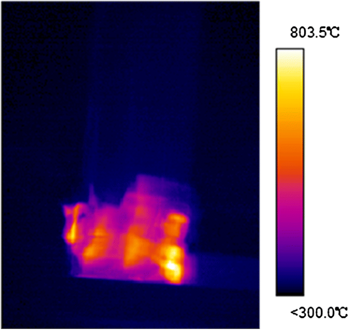
Cutting temperature recorded by the infrared thermal imager

Therefore, the cutting edge of the tool endures high tensile and compressive stresses as well as high temperature. The machined workpiece and the chip both have fresh surfaces with high chemical activity at high temperature. Meanwhile, the oxidation layer or other coating of the tool is worn gradually, which forms a condition for adhesion and diffusion of the tool and workpiece materials. Therefore, under the condition of interrupted machining, the uneven distribution state of cutting force and cutting temperature results in adhesive wear even the fracture of the tool. Higher cutting speed helps to decreases cutting force and is recommended to use in high speed milling of stainless steel.
3.2 Adhesive Wear Mechanism
3.2.1 Adhesion Condition
The reason that the adhesion of tool and chip is that there are strong affinity between the tool and chip materials. However, the tool’s coating can increase the wear-resistant performance and tool life. Only when the coating is worn, the adhesion can occur. Therefore, the coating wear should be investigated first when studying the adhesion condition.
The milling cutter has a sharp cutting edge with high cutting load. The cutting edge bears extrusion, shear and impact. Besides, the coating on the tool’s tip is weaker than other parts of the tool. Therefore, the cutting edge is more easily to be worn.
-
(1)
Coating wear
The cutting force in high-speed machining is usually smaller than conventional machining. However, as the cutting edge is very sharp, the load in unit area is very high.
The tool coating is TiAlN, which is a thin film coating and has a good mechanical performance and thermodynamic performance. TiAlN-coated tool is usually used in machining of difficult-to-cut materials. In the initial machining stage, the coating wear is slight and the surface is smooth. The wear scar has a smooth surface and shallow ploughing, and the distinct wear edge is seen, as shown in Figure 6.
Figure 6 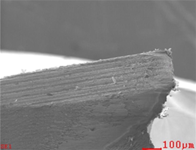
TiAlN coating in initial wear stage
The hardness of hard phase TiAlN in the coating is higher than the hard phase WC of the tool. The coating can restrict the diffusion of hard phase Cr and Mo, which can refine grains and increase the tool’s strength, increasing the wear resistance of the tool. As Al in the coating is easy to be oxidized to form Al2O3 dense membrane on the tool surface, the strength decreasing due to C diffusion and adhesion due to adhesive phase diffusion can be avoided to some extent. The resistance of diffusion wear and adhesive wear of the tool are therefore increased.
Refs. [23,24,25,26] show that under mechanical load, thermal impact and the effects of tearing of tool and chip, coating spallation is often found, which leads the coating failure and makes the naked tool matrix exposed to the air.
The experiment indicates the main wear form of TiAlN-coated tool is characterized as slight fracture of the tool edge. The coating spallation occurs in the cutting edge near the rake face. Adhesions and coating adhered on the tool edge are found. But the cutting edge is still sharp enough to continue working, as shown in Figure 7.
Figure 7 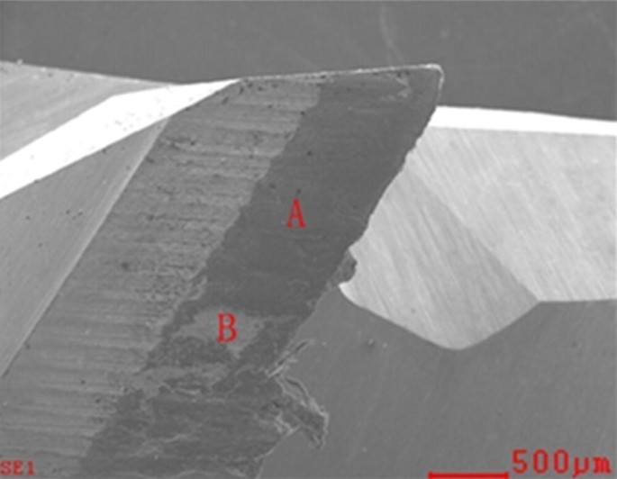
TiAlN coating in medium term of wear stage
The energy spectrum analysis on the coating area and spallation area of the rake face is shown in Figure 8. The TiAlN coating’s Al and Ti are the main elements in the coating area A of Figure 7, which proves that the coating remains good. The particles WC of the cemented carbide are the main element in the spallation area B of Figure 7, which proves that the coating is peeled off completely. The adhesive wear appears in the spallation area B as element Co cannot be detected. Co is removed by the chip due to the affinity with Fe.
Figure 8 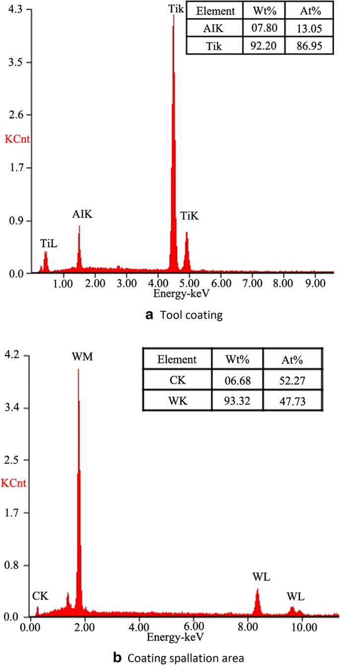
Energy spectrum analysis of coating area and spallation area
As discussed above, the mechanical load and the thermal impact result in spallation of the tool’s coating, and the adhesive wear is easy to occur, which is regarded as an important condition to cause adhesive wear of the coated tool.
-
(2)
Elements affinity between Fe and Co
Adhesive wear is a phenomenon which occurs when two materials rub together with sufficient force to cause the removal of material from the less wear-resistant surface [27]. The precondition of adhesive wear is the interaction between the tool and chip materials. The affinity between the tool and workpiece materials has a great effect on adhesion, and the affinity is proportional to the intersolubility of the tool and chip materials. Through the energy spectrum analysis, the elements of the workpiece and chip materials are found in the tool’s material. Thus, it is considered that the replacement reaction occurs between the tool and workpiece elements, thus the substituted solid solution is formed. From materials science knowledge, the atomic size, electronegativity and the location of element periodic table will affect the formation the substituted solid solution.
The tool used in the experiment mainly consists of hard phase WC and adhesive phase Co, and the affinity between the tool and workpiece materials depends on the content of adhesive phase Co. The workpiece material 0Cr13Ni4Mo mainly consists of Fe and Co. There is a certain affinity between Fe and Co, because the two elements are adjacent to each other in the periodic table. So they are similar in physical properties and easy to form substituted solid solution, as shown in Table 4.
Table 4 Comparison of physical properties of Fe and Co -
(3)
Grinding effects of workpiece material
In the machining process, the hard martensite in 0Cr13Ni4Mo results in the removal of adhesive phase Co on the surface. During the removal, the accumulation effect of dislocation pile-up is aggravated, which makes dislocation energy greater than cohesive energy between grains. Therefore, the nucleation of crack is formed. Under the cyclical load through abrasive particles, cracks nucleated on the surface of adhesive phase Co will eventually extend to the subsurface, and form fracture path between particles WC and micro fracture at last.
The grinding effects make soft adhesive phase Co drop from the tool and promote the replacement reaction between Fe and Co, which aggravates the replacement between tool and workpiece elements. On the other hand, cracks nucleated on the surface of adhesive phase Co will eventually extend to the WC particles. When the chip adhered on the tool suffers tensile stress in the milling process, the present cracks are easy to assist taking away material on the tool surface by chip.
Figure 8(a) and (b) respectively show the SEM micrographs of the rake face by magnifying 4000 times and 20000 times after milling. In Figure 9, gray areas are adhesive phase C, and hoary areas are particles WC. The original morphology of the cemented carbide tool has a dense structure with adhesive phase Co being evenly distributed around the particles WC. However, from Figure 9, it is seen that the cemented carbide tool has a loosen texture and decreased binder. Black hole around the particles WC is also found. It is concluded that grinding effects of workpiece material results in the removal of adhesive phase Co, and pits are formed. Under cyclical load of the grinding particles, the extended cracks in WC particles generate a loosen texture and decreased strength, which produces a condition for adhesive wear.
Figure 9 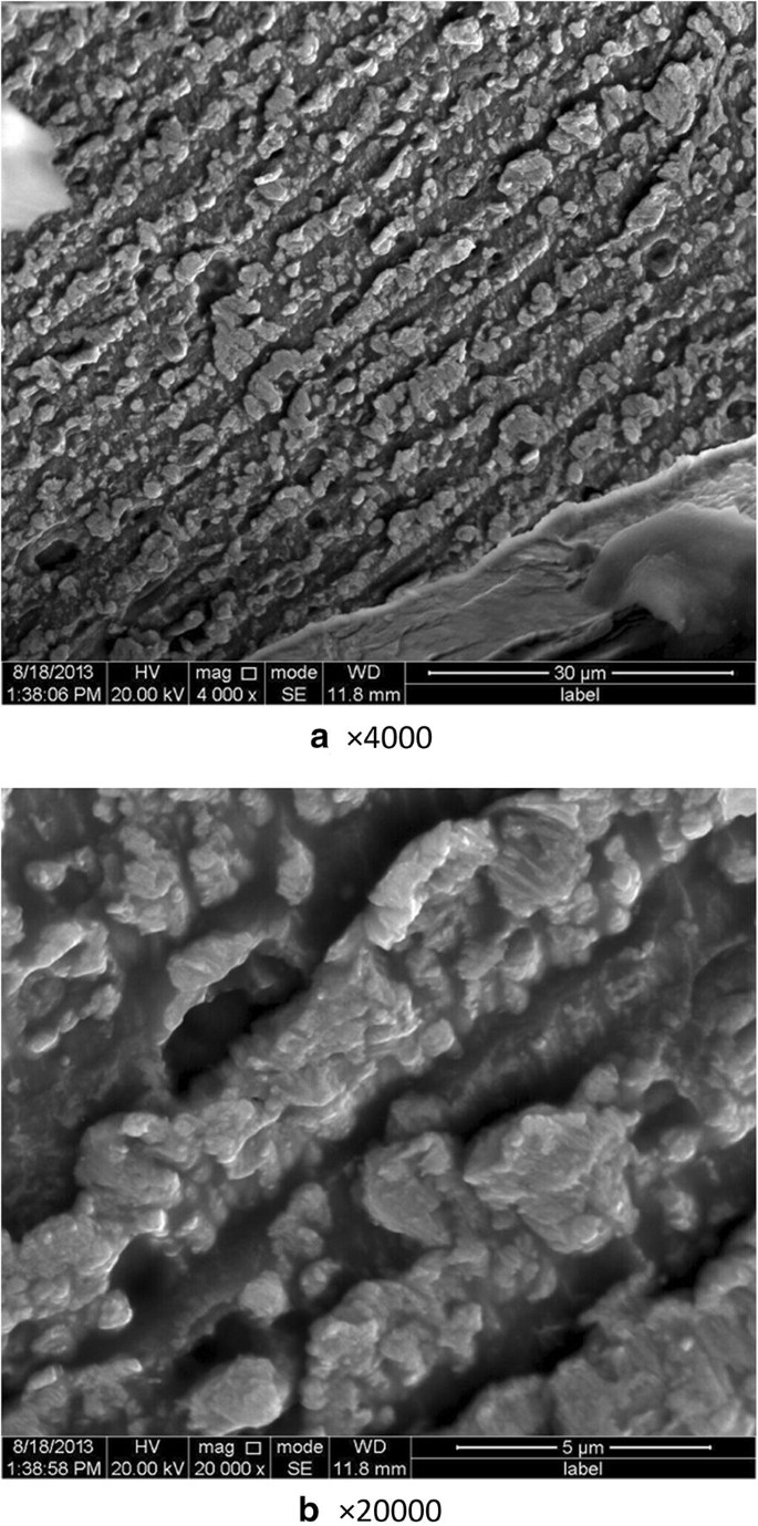
Morphology on the tool surface


3.2.2 Microcosmic Mechanism of Adhesive Wear
The energy spectrum analysis indicating the main chemical composition and content of each element on the rake face with adhesive wear is shown in Figure 10. According to the analysis, a large number of Cr, Fe, Mn and other elements can be observed in the area of adhesive wear. A lot of workpiece material elements are considered permeating into the tool by comparing with the chemical composition of stainless steel 0Cr13Ni4Mo in Table 1. Meanwhile, Co and WC are found in chips by energy spectrum analysis, which indicates adhesion and replacement reaction between the tool and workpiece.

Energy spectrum analysis of the rake face with adhesive wear
From the perspective of thermal stress, the compressive stress in cut-in process and cutting heat generate adhesion of tool and workpiece with some strength. Then the tensile stress generates tearing in cut-out process. As milling is a typical interrupted cutting process, alternate compressive stress and tensile stresses are applied to the tool. Unsteady temperature field is generated in the cutting area and thermal stress is also generated due to deformation. Under the effects of thermal stress and mechanical stress, the adhesive phase Co on the tool surface is removed and WC particles drops from the rake face and pits are formed. The accumulations process will cause tool failure finally.
Figure 11 shows the adhesive wear process of the rake face of the tool in milling of 0Cr13Ni4Mo. The record of high-speed camera shows that chips adhere on the rake face after several feeding periods. In the initial stage, the adhered chips distribute along the main cutting edge and rotate with the tool. Little accumulated chip can be found. Then large amount of accumulated chips are found on the rake face after several cut-in and cut-out process, as shown in Figure 11(a). The rectangle-shaped chips parallel to the cutting edge overlap together.

Adhesive wear process of the rake face of the tool
With the milling process, the chips along the cutting edge are torn from the rake face by tensile stress, as shown in Figure 11(b). The rake face and flank of the tool are both in integrated state. No collapse and depression is found. The machining process goes on well.
After a period of time of adhesion and tearing, the fracture of tool tip occurs. Material loss and holes on the rake face are found, as shown in Figure 11(c). However, the machining can still perform as the main cutting edge is sharp enough.
Later in the milling process, adhesive wear expands from tool tip to cutting edge and rake face, which results in the material loss of cutting edge and rake face. The tool will eventually lose cutting ability, as shown in Figure 11(d).
Figure 12 shows the adhered chips on the tool. Collected adhered chips in Figure 13 show a mixing of the tool and workpiece materials. Adhesive wear is the main reason causing cutting failure of the cemented carbide tool in high speed milling of 0Cr13Ni4Mo.

Adhered chip on the tool

Dropped chips from the tool
3.3 Analysis of Adhesive Wear Process
Figure 11 illustrates the process from the generation of adhesive chips to losing cutting ability, and the entire process of adhesive wear can be summarized. Based on the analysis of microcosmic and macroscopic process, the adhesive wear process can be divided into four stages as follows:
-
(1)
Friction and adhesion
The rake face is subjected to extrusion, shear, impact and friction in the milling. Then tool coating is worn gradually with the milling process. The affinity between Co and the Fe, high cutting force and high cutting temperature generate solid welding between the tool surface and micro-bulge on the workpiece surface. The contact of the rake face and chip is point-to-point contact. As the adhesion area is small, the adhesion is easy to drop.
-
(2)
Crack formation and propagation
In the milling process, the strong adhesion of the tool and chip can be found by the high-speed camera and SEM. The cracks inside adhesive phase Co and the cracks along the interface between hard phase WC and adhesive phase Co are formed under alternate stresses. The cracks continuously grow with the milling process and extend to the tool inside in vertical direction and to the tool surface in horizontal direction.
-
(3)
Adhesive wear
The formed micro-bulges drop due to external forces, and then the cracks generated by alternate stresses make local materials removed by adhered chips, forming pits on the rake face. As the crack formation and its propagation direction are random, adhesive wear is also random. Adhesive wear is first generated in some local areas and then fluctuant adhesive wear patterns are formed under reciprocating effects.
-
(4)
Tool failure
Adhesive wear is a cyclic process as follows: adhesion of tool and chip → element diffusion → cracks formation and propagation → tearing of the tool → re-adhesion → re-tearing → tool failure.
4 Conclusions
-
(1)
Adhesive wear of the tool is caused by wear of coating, the affinity of elements Fe and Co, and the grinding of workpiece materials to the tool material.
-
(2)
The process of adhesive wear includes both microcosmic elements diffusion and macroscopic cyclic process of adhesion, tearing and fracture, which can be summarized as four stages: friction and adhesion, crack formation and propagation, adhesive wear, and tool failure.
-
(3)
The adhesive wear of the tool is determined by the stress field, temperature field and tool surface wear. And the dropping of the soft adhesive phase Co is resulted by the cracks generated in the tool.
-
(4)
The tool strength is decreased by the cracks propagation in hard phase WC and adhesive phase Co. And adhesive wear is easier to occur under high tensile stress and high temperature gradient.
References
J X Deng, J T Zhou, H Zhang, et al. Wear mechanisms of cemented carbide tools in dry cutting of precipitation hardening semi-austenitic stainless steels. Wear, 2011, 270(7): 520–527.
F L Sun, Z J Li, D M Jiang, et al. Adhering wear mechanism of cemented carbide cutter in the intervallic cutting of stainless steel. Wear, 1998, 214(1): 79–82.
R M’saoubi, H Chandrasekaran. Innovative Methods for the investigation of tool-chip adhesion and layer formation during machining. CIRP Annals - Manufacturing Technology, 2005, 54(1): 59–62.
Z B Yin, C Z Huang, J T Yuan, et al. Cutting performance and life prediction of an Al2O3/TiC micro-nano-composite ceramic tool when machining austenitic stainless steel. Ceramics International, 2015, 41(5): 7059–7065.
M J Bermingham, D Kent, M S Dargusch. A new understanding of the wear processes during laser assisted milling 17-4 precipitation hardened stainless steel. Wear, 2015, s328-329: 518–530.
M Okada, A Hosokawa, N Asakawa, et al. End milling of stainless steel and titanium alloy in an oil mist environment. International Journal of Advanced Manufacturing Technology, 2014, 74(9-12): 1255–1266.
M Nalbant. Effect of cryogenic cooling in milling process of AISI 304 stainless steel. Transactions of Nonferrous Metals Society of China, 2011, 21(1): 72–79.
B D Jerold, M P Kumar. Machining of AISI 316 stainless steel under carbon dioxide cooling. Materials & Manufacturing Processes, 2012, 27(10): 1059–1065.
A Maurel-pantel, M Fontaine, G Michel, et al. Experimental investigations from conventional to high speed milling on a 304-L stainless steel. International Journal of Advanced Manufacturing Technology, 2013, 69(9-12): 1–23.
C A D O Junior, A E Diniz, R Bertazzoli. Correlating tool wear, surface roughness and corrosion resistance in the turning process of super duplex stainless steel. Journal of the Brazilian Society of Mechanical Sciences & Engineering, 2014, 36(4): 775–785.
N A Özbek, A Çiçek, M Gülesin, et al. Effect of cutting conditions on wear performance of cryogenically treated tungsten carbide inserts in dry turning of stainless steel. Tribology International, 2016, 94: 223–233.
G L Liu, B Zou, C Z Huang, et al. Tool damage and its effect on the machined surface roughness in high-speed face milling the 17-4PH stainless steel. International Journal of Advanced Manufacturing Technology, 2015, 83(1–4): 1–8.
H Kato, K Shintani, M Nakamura, et al. A study on the high-efficiency cutting of austenitic stainless steel using an HfN-type coated tool. Journal of Advanced Mechanical Design Systems & Manufacturing, 2012, 6(6): 829–840.
K Broniszewski, J Wozniak, K Czechowski, et al. Al2O3-Mo cutting tools for machining hardened stainless steel. Ceramics International, 2015, 41(10): 14190–14196.
G Y Tan, G J Liu, G H Li, et al. Adhesive failure of grooved tool in milling of 3Cr-1Mo-1/4V steel. International Journal of Materials & Product Technology, 2011, 42(3/4): 219–233.
S Saketi, J Östby, M Olsson. Influence of tool surface topography on the material transfer tendency and tool wear in the turning of 316L stainless steel. Wear, 2016, 368–369: 239–252.
J G Corrêa, R B Schroeter, R M Álisson. Tool life and wear mechanism analysis of carbide tools used in the machining of martensitic and supermartensitic stainless steels. Tribology International, 2017, 105: 102–117.
U Wiklund, S Rubino, K Kádas, et al. Experimental and theoretical studies on stainless steel transfer onto a TiN-coated cutting tool. Acta Materialia, 2011, 59(1): 68–74.
W Y H Liew. Low-speed milling of stainless steel with TiAlN single-layer and TiAlN/AlCrN nano-multilayer coated carbide tools under different lubrication conditions. Wear, 2010, 269(7–8): 617–631.
S Y Ma, R Chen, X C He, et al. Shot peening induced strengthening of the surface layer of martensite stainless steel 0Cr13Ni4Mo. Acta Metallrugica Sinica, 2005, 41(1): 28–32.
K A Abou-el-hossein, Z Yahya. High-speed end-milling of AISI 304 stainless steels using new geometrically developed carbide inserts. Journal of Materials Processing Technology, 2005, s162-163(10): 596–602.
C Zhang, L S Zhou. Modeling of tool wear for ball end milling cutter based on shape mapping. International Journal for Interactive Design & Manufacturing, 2012, 7(3): 171–181.
Y B Guo, W Li, I S Jawahir. Surface integrity characterization and prediction in machining of hardened and difficult-to-machine alloys: a state-of-art research review and analysis. Machining Science & Technology, 2009, 13(4): 437–470 (34).
P M D Escalona, P G Maropoulos. Influence of cutting parameters and tool wear on martensitic stainless steel surface integrity after a face milling process. ASME 2009 Pressure Vessels and Piping Conference. American Society of Mechanical Engineers, 2009: 1707–1716.
W Y H Liew, X Ding. Wear progression of carbide tool in low-speed end milling of stainless steel. Wear, 2008, 265(1–2): 155–166.
A E Diniz, R M Álisson, J G Corrêa. Tool wear mechanisms in the machining of steels and stainless steels. International Journal of Advanced Manufacturing Technology, 2016, https://doi.org/10.1007/s00170-016-8704-3
B Bharat. Tribology and mechanics of magnetic storage devices. Journal of Tribology, 1990, 112(3): 278.
Authors’ Contributions
G-HL and G-YT was in charge of the whole trial; G-JL and Z-CZ wrote the manuscript; XQ and W-HP assisted with sampling and laboratory analyses. All authors read and approved the final manuscript.
Authors’ Information
Guang-Jun Liu, born in 1979, is currently an associate professor at School of Mechanical Engineering, Tongji University, China. His research interests include high-speed hard machining and high-speed cutting tools.
Zhao-Cheng Zhou, born in 1991, is currently a master candidate at School of Mechanical Engineering, Tongji University, China.
Xin Qian, born in 1993, is currently a master candidate at School of Mechanical Engineering, Tongji University, China.
Wei-Hai Pang, born in 1976, is currently a lecturer at College of Environmental Science and Engineering, Tongji University, China. His research interests are in the areas of water treatment equipment.
Guang-Hui Li, born in 1960, is currently a Professor at School of Mechanical and Power Engineering, Guangdong Ocean University, China. Her research interests include high speed machining and rapid prototyping.
Guang-Yu Tan, born in 1957, is currently a Professor at School of Mechanical and Power Engineering, Guangdong Ocean University, China. His research interests include metal cutting theory, tool design, high speed machining, as well as numerical simulation and optimization.
Competing Interests
The authors declare no competing financial interests.
Funding
Supported by National Natural Science Foundation of China (Grant No. 51375099), Shanghai Municipal Natural Science Foundation of China (Grant No. 18ZR1441000), and Fundamental Research Funds for the Central Universities.
Publisher’s Note
Springer Nature remains neutral with regard to jurisdictional claims in published maps and institutional affiliations.
Author information
Authors and Affiliations
Corresponding author
Rights and permissions
Open Access This article is distributed under the terms of the Creative Commons Attribution 4.0 International License (http://creativecommons.org/licenses/by/4.0/), which permits unrestricted use, distribution, and reproduction in any medium, provided you give appropriate credit to the original author(s) and the source, provide a link to the Creative Commons license, and indicate if changes were made.
About this article

Cite this article
Liu, GJ., Zhou, ZC., Qian, X. et al. Wear Mechanism of Cemented Carbide Tool in High Speed Milling of Stainless Steel. Chin. J. Mech. Eng. 31, 98 (2018). https://doi.org/10.1186/s10033-018-0298-2
Received:
Accepted:
Published:
DOI: https://doi.org/10.1186/s10033-018-0298-2