- Original Article
- Open access
- Published:
Remanufacturing Scheme Design for Used Parts Based on Incomplete Information Reconstruction
Chinese Journal of Mechanical Engineering volume 33, Article number: 41 (2020)
Abstract
The different conditions of use of a component result in a variety of damage levels. Therefore, excluding differences in shape and size, used parts show a high degree of uncertainty regarding failure characteristics, quality conditions, and remaining life, which seriously affects the efficiency of a remanufacturing scheme design. Aiming to address this problem, a remanufacturing scheme design method based on the reconstruction of incomplete information of used parts is proposed. First, the remaining life of the reconstructed model is predicted by finite element analysis, and the demand for the next life cycle is determined. Second, the scanned 3D damage point cloud data are registered with the original point cloud data using the integral iterative method to construct a missing point cloud model to achieve the restoration of geometric information. Then, according to reverse engineering and laser cladding remanufacturing, the tool remanufacturing process path can be generated by the tool contact point path section line method. Finally, the proposed method is adopted for turbine blades to evaluate the effectiveness and feasibility of the proposed scheme. This study proposes a remanufacturing scheme design method based on the incomplete reconstruction of used part information to solve the uncertain and highly personalized problems in remanufacturing.
1 Introduction
Remanufacturing is a process that returns used parts into “new or better than new” performance and conditions and includes disassembling, cleaning, repair, reassembly, and inspection [1]. However, in addition to differences in shape and size, used parts exhibit a high degree of uncertainty in terms of failure characteristics, quality conditions, and remaining life [2]. The sound design of the remanufacturing scheme is one of the key steps to improve remanufacturing efficiency and reduce production costs. It not only allows the reutilization of used parts but also helps to save money and resources and protect the environment [3,4,5].
A remanufacturing scheme design uses advanced manufacturing techniques to repair used parts, so as to achieve low cost, high efficiency, high reuse rate, and performance recovery upgrade [6, 7]. A premise for the remanufacturing scheme is to understand the information on the failure characteristics of used parts. In general, the common failure modes of used parts include fracture, wear, and deformation, which account for more than 75% of the total failures of parts [8, 9]. Owing to the long-term service, wear, and loss of technical documentation, it is difficult to obtain the technical information of the parts, which results in differences in remanufacturing schemes and affects the quality of remanufacturing [10,11,12,13,14]. At present, the design of remanufacturing schemes is still based on personnel experience and manuals, which leads to difficulties in remanufacturing efficiency, cost, and energy consumption, and there are a series of scientific problems that need to be solved [15,16,17,18]. Therefore, a reasonable remanufacturing scheme can effectively improve the efficiency and reduce costs. Understanding the failure characteristics of used parts is of great significance to achieve high efficiency and strict quality requirements.
The purpose of this study is to generate rapidly and efficiently a remanufacturing scheme. Compared with previous studies, the novelty of this work lies in the following aspects: 1) A framework for a remanufacturing scheme design based on incomplete information reconstruction is developed. 2) By means of finite element analysis, the remaining life of the reconstructed model is predicted, and the requirements of the next life cycle are assessed. 3) By using an integral iteration method, the 3D scanned damage point cloud data is registered with the original point cloud data, and the missing point cloud model is constructed to achieve geometric information recovery. 4) A cladding path is generated for the recovered part model using the tool contact point path section line method.
This paper is organized in five sections. The first section introduces the remanufacturing design. The literature on remanufacturing scheme design is reviewed in Section 2. The third section explains in detail the method used. The fourth section takes a remanufactured turbine blade as an example to verify the effectiveness of the method. The fifth section summarizes and discusses the results of the case study to draw the conclusions of this study.
2 Literature Review
The development of a remanufacturing scheme is essential for the remanufacturing processes. It directly affects the remanufacturing production efficiency, cost, and energy consumption, and it is important to maximize the utilization of the residual value of used parts. Owing to the differences in load conditions and environmental media during product service life, used parts possess varying failure characteristics such as wear, fracture, and corrosion, which affect the remanufacturing processes. Therefore, to maximize the remanufacturing efficiency and cost-effectiveness, it is of paramount importance to develop a remanufacturing scheme that fully considers the unique failure characteristics of the used parts to be remanufactured.
The remanufacturing process planning and optimization and decision making over the remanufacturability of used parts have been studied in the literature. Li et al. [19] proposed a decision-making method for the remanufacturing process based on an improved fuzzy neural network, which comprehensively considered the uncertainty and ambiguity of the damage condition of used parts for remanufacturing and the quality requirements after remanufacturing. Jiang et al. [20] proposed a remanufacturing process planning method that combines rough sets and case-based reasoning and rapidly creates a process planning for used parts from the knowledge generated from existing parts remanufacturing. Zhang et al. [21] studied the process planning and scheduling problem of a typical remanufacturing system based on the difficulties and complexities brought about by various uncertainties in the remanufacturing processes, and they developed a multi-objective genetic algorithm based on simulation. Zheng et al. [22] proposed a hybrid method that combines coordinate measuring machine data acquisition, defect model regeneration, and repair process selection decisions for complex damage parts with various defects. Jiang et al. [23] developed a process planning decision method considering the ambiguity of remanufacturing performance standards and the inherent complexity associated with process planning decisions. A decision method combining quality function deployment and fuzzy linear regression was proposed to determine the most appropriate process plan. Kin et al. [24] analyzed the conditions and defects of the core components and determined the optimal repair process of these components. Chao et al. [25] established an effective method linking 3D point cloud reconstruction and laser metal deposition repair and proposed a method for remanufacturing damaged metal parts using the additive manufacturing technology. To improve the final quality of parts obtained by additive manufacturing, Um et al. [26] proposed a method of additive manufacturing representation based on a step neural network and a series of geometric reasoning methods to realize the automatic derivation of the repair section. Zhang et al. [27] proposed a modeling method for the repair of wear, edge crack, distortion, creep, and corrosion of aero-engine blades, and the effectiveness of the proposed method was verified by repair experiments. Wilson et al. [28] provided an attractive and cost-effective method for repair or remanufacturing of high-value engineering components through laser direct deposition techniques, in which turbine airfoil defects were successfully repaired using a new semi-automated geometric reconstruction algorithm and a laser direct deposition process.
Various fault characteristics lead to the need for customized solutions, and thus, a rapid and accurate acquisition of the fault characteristics can help improve the remanufacturing efficiency. Li et al. [29] targeting at the individuality of the failure condition and the complexity of the structure and shape of the worn mechanical parts in a remanufacturing system, proposed a reverse engineering-assisted remanufacturing integration method for the worn parts. Eyup et al. [30] used a coordinate measuring machine to capture the important scan lines on the surface of the damaged component and then construct the feature outline of the parts for remanufacturing. Zhang et al. [31] suggested a new approach that took into consideration the working conditions, structural characteristics, and loading distribution and analyzed the causes of fracture failure based on the finite element method. Hou et al. [32] investigated the repair of worn blades. The manual acquisition of the target surface is very time consuming, and thus, an innovative adaptive maintenance strategy was proposed, covering the pre-inspection, welding, and machining processes.
The previous works have provided effective solutions addressing the uncertainty and individuality of the failure conditions of used products. However, there are several steps in the restoration that are isolated. There are limited interactions between the restoration steps, resulting in an ad-hoc remanufacturing restoration. This paper proposes a remanufacturing scheme design method based on incomplete information reconstruction of second-hand parts. First, through finite element analysis, the remaining life of the reconstruction model can be predicted, and it can be determined whether the demand for the next life cycle is met. Second, by analyzing the incomplete and fuzzy component remanufacturing information, the missing point cloud model is constructed to recover the geometric information. Finally, the tool remanufacturing process path can be generated by the tool contact point path section line method.
3 Remanufacturing Design Framework
Owing to the diversity in remanufacturing technologies and the complexity of the design of a repair solution, it is important to select a suitable remanufacturing process and design a repair solution. A design framework for the remanufacturing scheme design for used parts based on the reconstruction of defective information is established as shown in Figure 1.

Remanufacturing design framework for used parts
The first step for remanufacturing used parts is to pre-test before remanufacturing to assess whether they meet the remanufacturing requirements. Geometric information reconstruction is performed on the used parts that meet the remanufacturing requirements. According to the principle of reverse engineering, the defect model of the part is extracted through 3D scanning, and the unit step integral iteration method is used to rapidly and efficiently register the defect point cloud data with the original data, and obtain the damage point cloud information through information reconstruction. Finally, the tool contact point path section line method is used to generate the repair path according to the identified missing point cloud.
3.1 Analysis and Modeling of Incomplete Information
-
(1)
Incomplete information classification
The information describing defects mainly includes geometric information, such as the wear state, and residual information, such as residual stress, as shown in Figure 2.

Incomplete information of used parts
During the service period, the surfaces of the component are affected by the inevitable wear, corrosion, and impacts, which lead to external damage, resulting in a change of the geometry and accuracy of the shape.
Besides, exposed to various working conditions, parts might fail due to residual stress, fatigue cracks, etc. This can be reflected in the internal microstructure of the material and macroscopic mechanical properties, such as strength, stiffness, wear-resistance, and corrosion resistance. The remaining life of parts can be measured by the internal microstructure and macroscopic mechanical properties.
- (2)
Geometry modeling of defective parts
Defect information is obtained by comparing the defect model with the original model as a reference for size and shape recovery.
The used parts may have defects, such as partial fracture, wear, or deformation. Thus, the point cloud model of the collected used parts cannot directly reflect the original shape of the used parts. The reverse modeling method can be used to perform the component averaged point cloud model using a Power Scan-Pro precision 3D scanner that combines the structured light, phase measurement, and computer vision technologies. This 3D scanner, shown in Figure 3, enables high-speed, high-density measurements of components and outputs a 3D point cloud for further post-processing.

Data acquisition equipment and processing
3.2 Restoration Technology for Incomplete Information
The reconstruction of incomplete information on used parts can effectively support the design of remanufacturing solutions. Therefore, the restoration of incomplete information of used parts is a prerequisite for the design of the remanufacturing scheme.
3.2.1 Prediction of Remaining Life
Used parts are affected by various working conditions during use that result in residual stress, fatigue cracks, and other factors affecting their quality and reliability. As a consequence, their remaining life may not meet the remanufacturing requirements.
The differences in working conditions of parts and components lead to uncertainty about their residual fatigue life. Therefore, the remaining fatigue life can be used to determine whether there is sufficient service life for the used parts. Life expectancy is critical for decision making of the remanufacturing worthiness; a remanufactured part without sufficient service life may lead to potential quality problems and safety hazards. Through life expectancy prediction and by judging whether the remanufacturing requirements are met, the quality problems and the probability of failure of remanufactured products during their service cycle will be greatly reduced. Therefore, judging whether the next life cycle requirements are met based on the remaining fatigue life of the old parts will undoubtedly improve the remanufacturing quality and contribute to the design theory of remanufacturing and repair of used parts.
For modeling of life expectancy, the mechanical properties and residual fatigue life are examined by finite element analysis. The data obtained could be used to determine whether the used parts meet the next life cycle requirements.
Based on the fatigue life prediction method of finite element simulation, the corresponding fatigue life prediction process of defective parts is established, as shown in Figure 4.

Life analysis process of used parts based on finite element analysis
Through the finite element analysis, the local stress distribution and fatigue life parameters of the parts are obtained and compared with their service life. The remaining life information of the parts can be obtained, and accordingly, it can be judged whether the used parts can satisfy the next life. The finite element analysis process is shown in Figure 5.

Finite element analysis process
3.2.2 Geometric Information Recovery Model
Based on reverse engineering, the worn part data (point cloud or triangular mesh surface) are collected. The two-dimensional planes of the three-dimensional model of the component are segmented and matched to determine the damaged area, and the damage depth is determined through three-dimensional reconstruction. The original point cloud model is reconstructed as shown in Figure 6.

Surface information recovery process based on reverse engineering
First, the actual point cloud image of the damaged parts is obtained through three-dimensional scanning. Second, an average component model is constructed, the outer surface region is divided into a mesh, and the relationship between the original model and damaged region mesh nodes is established; the node data are divided into two-dimensional planes. According to the node matching of the two-dimensional planes, the damaged node information is generated on the two-dimensional plane, and the damaged area is determined.
The unit step integration iteration method is used for differential registration. The error of the damage region is fitted by point cloud coordination to improve the accuracy of registration.
- 1)
Establishment of the 2D model and determination of damaged area
- a.
Definition of the damage-point coordinates
For the damaged component, the intersection of the mesh and the damaged section is defined, which can be represented by the geometry coordinates:
$$P_{i} = (x_{i} ,y_{i} ),i = 1,2, \ldots ,n,n + 1,$$(1)where Pi represents a node, xi represents the x coordinate value of the ith node on the damaged plane, and yi represents the y coordinate value of the ith node on the damaged plane.
- b.
Definition of a linear equation between every two sets of nodes
As n + 1 different nodes are determined, a different function expression is obtained. The function expression \(E_{{q_{i} }}\) between the nth and (n + 1)th nodes is defined as
$$f_{i} \left( {x,y} \right) = k_{i} x + b_{i} ,i = 1,2 \ldots n,$$(2)where ki represents the slope of the ith equation; bi represents the point at which the ith equation intersects the y-axis.
- c.
Determination of location of the damaged area
The definite integral of the function expression is calculated to obtain the region separated by the linear equation. The values of the regions are summed to obtain the total area of the damaged portion and determine the location of the damaged area, as presented in Figure 7.
Figure 7 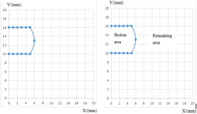
Meshing and damage location meshing and identification
- a.
- 2)
Establishment of the 3D model and determination of damage amount
The integral iteration method is proposed to recover the surface defect information. The process is depicted in Figure 8.
Figure 8 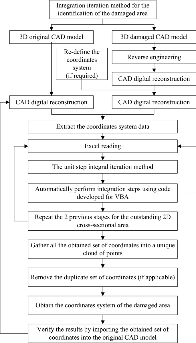
Damage model reconstruction process based on the unit step integral iteration method
The main steps are as follows:


Step 1: Generation of part grid.
The original model geometry is defined and meshed using SolidWorks. The grid size is defined, the grid is constructed based on the existing average point cloud model of parts, and the outer surface area is segmented to form the part model with known regional information. Its geometry is defined in the three planes of the x, y, and z axes.
Step 2: Extraction of data.
The defect model is preprocessed, and the three-dimensional model of the used part meshes is generated. The corresponding relationship between the three-dimensional coordinate axis and the model is established. The coordinates of the defective mesh nodes are derived.
Step 3: Determination of defective areas.
The original data and the coordinate set of the damaged area are exported. As the obtained original model and the damaged blade model have different coordinate sets, the three-dimensional plane of the component model is divided into two two-dimensional planes. The two sets of coordinates are compared using an integral iteration method to determine the damaged area. The flow of the integral iterative method is presented in Figure 9.

Integral iterative process
Step 4: Determination of the degree of matching.
If the matching degree is met, the next step can be performed; if not, the model coordinate system is modified and then matched.
Step 5: Generation of the amount of disability.
According to the above steps, the node coordinates of the defective used parts are obtained, and the defect amount of the component can be calculated.
Step 6: Model reconstruction.
The damaged area on the Z-X cross-section can be expressed as
where Ai represents the damaged area in the Z-X cross-section from the ith to the (i + 1)th nodes.
The depth of damage on the Y–X cross-section can be expressed as
where Vi represents the volume of the damaged region from the ith to the (i + 1)th nodes.
The damage model reconstruction process is shown in Figure 10.

Schematic diagram of damage model reconstruction
- (3)
Discrimination between matching model and source model
To judge the matching degree of the shape of the two models, the error is compared with the newly generated surface by the ranging method. Its form is defined as
where
The Hausdorff ranging method is used to compare the error of the reconstructed surface. On the surface \(S_{0} (u,v)\), the sample points are set to \(A = (a_{1} , \ldots ,a_{n} )\). On the surface \(S_{1} (u,v)\), the upper step sampling point is set to \(B = \left( {b_{1} , \ldots b_{m} } \right)\); then, the Hausdorff distance between the two surfaces of \(S_{0}\) and \(S_{1}\) is \(H(A,B)\). The basic steps are shown in Figure 11.

Discrimination process of the reconstruction model and source model matching degree
3.2.3 Generation of Machining Paths
Taking laser cladding as an example, a cladding path is generated for the recovered part model using the tool contact point path section line method. A series of intersecting lines are obtained by cutting a parallel surface of a curved part into a plane or a curved set. These lines are the projection lines of the processing head trajectory on the surface of the parts. It is assumed that cladding occurs when the laser spot size remains the same, and the surface is evenly scanned in a certain order. In practice, isometric plane methods are available for determining the cladding track on the surface of projection line, as shown in Figure 12(a). The determination of the tangent plane distance of the cladding trajectory is the key to finding the cladding trajectory. The flatness of the macroscopic surface of the cladding layer is mainly affected by the lap joint, and the theoretical lap joint model is established as shown in Figure 12(b). The pitch of the tangent plane is analyzed and calculated. w is the width of a single cladding layer, h is the height, the centers of the adjacent two claddings (the center of the spot) are O1 and O2, respectively, and d is the distance between centers of the adjacent two cladding tracks (O1O2). \(h_{S}\) is the height difference between the peak and the trough of the surface after the lap, and d is the tangential plane spacing.

(a) Trajectory generated with cutting plane method; (b) Theoretical lap mode
3.3 Remanufacturing Scheme Design
Through the reconstruction of the missing information of the parts, the point cloud nodes that generate the damage can provide the coordinate basis of the processing path for the remanufacturing scheme design and rapidly and accurately develop the optimal remanufacturing scheme for different used parts.
By registering the damage model of the used parts obtained by three-dimensional scanning with the original model, the defect amount of the damage model is obtained, and then the remanufacturing repair process path is generated by the point cloud information of the defect amount, as shown in Figure 13.

Schematic diagram of damage model reconstruction
To accelerate and simplify the computational process of the remanufacturing repair, the code is generated by Microsoft Visual Basic for Applications and run on Excel. The routing is generated as follows.
- a.
Determination of the 3D graphics
The missing node coordinates for the cross-sectional area are collected and the node coordinates needed to repair the 3D graphics are extracted from Excel. The 3D graphics required to repair the used parts are determined by these nodes.
- b.
The geometric entities generated by the point cloud are imported into SolidWorks
This step converts the visual image of the node during the repair process into the required 3D graphics, reconstructs the 3D graphics into a solid geometry, and then displays the entities in SolidWorks. As the entities represented by these points are the damaged parts, the damage geometric entities are composed of point cloud data.
- c.
Laser cladding machining path generation
The thickness of the laser cladding layer required to reconstruct the damaged portion of the model is determined by the height difference between each point. The extent of the damage zone is determined by the missing point cloud on the same plane. Finally, the cladding path is generated for the recovered part model using the tool contact point path section line method, and the used parts are remanufactured as blanks.
4 Case Study
Turbine blades are important transmission components in mechanical engineering. Due to the influence of service conditions, materials, and structures, it is easy to cause tooth surface fatigue damage, tooth surface wear, and fracture failure. Turbine blades have a long manufacturing cycle with high added value. As shown in Figure 14, the design steps of the blade remanufacturing scheme are described by taking a certain type of turbine blade as an example and the GH4133 alloy as its material.

Physical drawing of turbine blade
- (1)
Finite element analysis of reconstructed models
As can be observed in Figures 15 and 16, the design life of the turbine blade is 1000 SI, and the fatigue life of the finite element calculation reconstruction model is 1300 SI, which can meet the remanufacturing requirements.

Stress distribution cloud

Fatigue life cloud
- (2)
Meshing
The original 3D scan model and the damage 3D model mesh of the used parts are shown in Figures 17 and 18. According to the defined size, the original 3D scan model has 1974 nodes with different coordinates.

Turbine blade original model

Turbine blade damage model
The mesh size selected for the used component model is 0.91 mm, and 6650 nodes are obtained.
- (3)
Identification of cutting coordinates
The coordinates of the original 3D model nodes are then exported to Excel, where the coordinates of the 1974 different points of the blade are obtained. Some of the data are listed in Table 1.
The obtained damage model nodes and their respective coordinates are listed in Table 2.
Comparing the original and corrupted coordinate sets, the three-dimensional model of the blade is divided into two two-dimensional planes by the unit integral iteration method, as shown in Figure 19.

Two-dimensional display of turbine blade damage model
- (4)
Generation of tool path
The missing nodes are obtained by the algorithm to determine the original missing model of the turbine blade. Table 3 is an excerpt from the coordinates of the nodes of the damaged blade. In total, 394 nodes of the original model are missing.
According to the identified missing point cloud, an incomplete entity is generated. The coordinates and normal vector of the welding points are calculated by the tool contact point path hatching method, and the coordinates and attitude of the machine gun head at each point are obtained. It is necessary to ensure that, with the robot processing attitude, the laser beam is perpendicular to the processing surface. However, in the actual machining, the laser beam axis and the normal of the processing surface should have a certain angle to avoid laser beam reflection into the processing head, which would cause damage to the optical path. The tip of the gun should be prevented from melting after the end of cladding. If the angle is too large, it would cause accumulation and jitter, thus affecting the surface quality. Generally, the path is extended outward by a distance, and then the points are sequentially connected to obtain the processing trajectory, as shown in Figure 20.

Determination of nozzle path
The set of coordinates needed to repair the path is extracted from Microsoft Excel and is imported as a curve into SolidWorks through the XYZ point function to generate the final machining path, as presented in Figure 21.

Laser cladding processing path
In this study, iso-parametric tool-path planning [33] is used to plan the machining path. The tool trajectory map obtained by iso-parametric tool-path planning is used for the generation of machining, as shown in Figure 22.

Machining path generated by iso-parametric tool-path planning
The trajectory line length is an important parameter for evaluating the tool trajectory. Once the trajectory is generated, its length is easily calculated. The trajectory lengths of the iso-parametric tool-path planning and point contact methods are calculated separately, and the results are presented in Table 4.
It can be observed from Table 4 that the tool contact point path section line method is shorter, mainly because the path spacing is determined by the curvature of the processing surface when the other processing parameters are the same. The iso-parametric tool-path planning is the minimum distance between two adjacent trajectory lines, and thus, the overall trajectory line will appear dense and the number of trajectory lines will increase significantly. Therefore, the total length will increase significantly.
- (5)
Error analysis
- a.
Error analysis of simulation models
To verify the geometric quality of the digital model of the compressor blade after remanufacturing, several blade sections should be compared before and after repair. First, on the pressure and suction surfaces of the blade model before repair, leaf slices are taken with 10 planes and the boundary curves A and B are extracted. Then, it is rotated to the corresponding position of the blade repair target model by coordinate rotation. The normal distances from the boundary curves A and B to the pressure and suction surfaces of the repaired blade model are found, and the maximum distance is taken to draw the error curve. In the same way, error curves are established for the leading and trailing edges of the blade model, as shown in Figures 23 and 24.
Figure 23 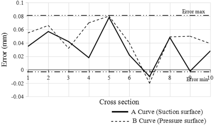
Error of A and B curves
Figure 24 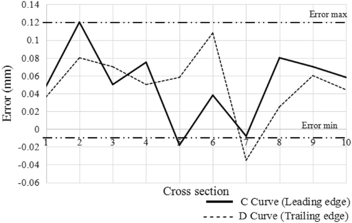
Error of C and D curves
In Figures 23 and 24, it can be observed that, compared with the pre-repair model of the blade repair target model, the maximum deviation of curves A and B is 0.08 mm and the minimum deviation is − 0.002 mm; the maximum deviation of curves C and D is 0.12 mm, and the minimum deviation is − 0.008 mm. The results reveal that the 3D model not only has good smoothness but also reflects the shape characteristics of the blade edges.
- a.
- b.
Error analysis of blade after remanufacturing
Comparing some related parameters of the remanufactured blade with the error requirements in the engine manual, as presented in Table 5, the results prove the feasibility of the remanufacturing repair scheme proposed in this study.
Table 5 Comparison of key parameters of the blade between the remanufactured and manual’s data From the analysis, the reasons for the errors are as follows. 1) The blade’s geometry has deviated from the original design shape for a long time in high temperature and high-pressure environments. 2) The process of 3D model reconstruction data processing will inevitably generate a certain accumulation error. 3) Different processing technology parameters will also affect the final repair accuracy of the blade.


5 Conclusions
-
(1)
By analyzing the failure characteristics of used parts, this paper proposes a remanufacturing scheme design method based on incomplete information reconstruction by analyzing typical failure characteristics of damaged blades. Taking turbine blades as an example, the results prove that it effectively solves a series of time-consuming and labor-intensive problems such as dimensional measurement, remanufacturability evaluation, and processing path generation, which improves the remanufacturing efficiency of used parts while ensuring the quality of remanufacturing.
-
(2)
The residual life of the used parts is analyzed by the finite element method, and the evaluation of whether the used parts meet the remanufacturing standards can guide the use of the residual value of the parts.
-
(3)
The integral iteration method is used to register the scanned 3D damage point cloud data with the original point cloud data, construct a missing point cloud model, and realize the restoration of geometric information. The results show that this method can effectively guarantee the remanufacturing quality of used parts.
-
(4)
After remanufacturing, the blades are tested for accuracy and error analysis. The results show that the geometric accuracy can meet the requirements of the maintenance manual, thus proving the feasibility of the method proposed in this paper.
References
G D Hatcher, W L Ijomah, J F C Windmill. Design for remanufacture: a literature review and future research needs. Journal of Cleaner Production, 2011, 19(17): 2004-2014.
M L Junior, M Godinho Filho. Production planning and control for remanufacturing: exploring characteristics and difficulties with case studies. Production Planning and Control, 2016, 27(3): 212-225.
W Shi, K J Min. Product remanufacturing: A real options approach. IEEE Transactions on Engineering Management, 2014, 61(2): 237-250.
Z G Jiang, Z Y Ding, H Zhang, et al. Data-driven ecological performance evaluation for remanufacturing process. Energy Conversion and Management, 2019, 198: 111844.
X G Zhang, H Zhang, Z G Jiang, et al. An integrated model for remanufacturing process route decision. International Journal of Computer Integrated Manufacturing, 2015, 28(5): 451-459.
X G Zhang, H Zhang, Z G Jiang, et al. Remanufacturing scheme decision model and application based on remaining useful life estimation. Journal of Mechanical Engineering, 2013, 49(7): 51-57. (in Chinese)
Z G Jiang, H Zhang, J W Sutherland. Development of multi-criteria decision-making model for remanufacturing technology portfolio selection. Journal of Cleaner Production, 2011, 19(17-18): 1939-1945.
H Wang, Z G Jiang, H Zhang, et al. An integrated MCDM approach considering demands-matching for reverse logistics. Journal of Cleaner Production, 2019, 208: 199–210.
M E Stevenson. Tools & techniques of failure analysis. Journal of Failure Analysis and Prevention, 2016, 16(3): 325-325.
C Tao, Y He, X Liu. Modern failure analysis techniques. Beijing: National Defense Industry Press, 2011.
H Wang, Z G Jiang, X G Zhang, et al. A fault feature characterization based method for remanufacturing process planning optimization. Journal of Cleaner Production, 2017, 161: 708-719.
C H Liu, Q Zhu, F Wei, et al. An integrated optimization control method for remanufacturing assembly system. Journal of Cleaner Production, 2020, 248: 119261.
D J Chen, Z G Jiang, S Zhu, et al. A knowledge-based method for eco-efficiency upgrading of remanufacturing process planning. The International Journal of Advanced Manufacturing Technology, 2020: 1-10.
Z Y Ding, Z G Jiang, H Zhang, et al. An integrated decision-making method for selecting machine tool guide ways considering remanufacturability. International Journal of Computer Integrated Manufacturing, 2018: 1-12.
İ Yanikoğlu, M Denizel. The value of quality grading in remanufacturing under quality level uncertainty. International Journal of Production Research, 2020: 1-21.
C H Liu, Q H Zhu, F F Wei, et al. A review on remanufacturing assembly management and technology. International Journal of Advanced Manufacturing, 2019, 105(11): 4797-4808.
Y Chen, F R Chen. On the competition between two modes of product recovery: Remanufacturing and refurbishing. Production and Operations Management, 2019, 28(12): 2983-3001.
Q S Gong, H Zhang, Z G Jiang, et al. Nonempirical hybrid multi-attribute decision-making method for design for remanufacturing. Advances in Manufacturing, 2019, 7(4): 423-437.
C B Li, Y Feng, Y B Du, et al. Decision-making method for used components remanufacturing process plan based on modified FNN. Computer Integrated Manufacturing Systems, 2016, 22(3): 728-737.
Z G Jiang, Y Jiang, Y Wang, et al. A hybrid approach of rough set and case-based reasoning to remanufacturing process planning. Journal of Intelligent Manufacturing, 2019, 30(1): 19-32.
R Zhang, S K Ong, A Y C Nee. A simulation-based genetic algorithm approach for remanufacturing process planning and scheduling. Applied Soft Computing, 2015, 37: 521-532.
Y Zheng, A J Qureshi, R Ahmad. Algorithm for remanufacturing of damaged parts with hybrid 3D printing and machining process. Manufacturing Letters, 2018, 15PA: 28-41.
Z G Jiang, F Zhou, J W Sutherland, et al. Development of an optimal method for remanufacturing process plan selection. The International Journal of Advanced Manufacturing Technology, 2014, 72(9-12): 1551-1558.
S T M Kin, S K Ong, A Y C Nee. Remanufacturing process planning. Procedia CIRP, 2014, 15: 189-194.
F Chao, J Liang, C Y Gong, et al. Repair volume extraction method for damaged parts in remanufacturing repair. The International Journal of Advanced Manufacturing Technology, 2018, 98: 1523-1536.
J Um, M Rauch, J Y Hascoët, et al. STEP-NC compliant process planning of additive manufacturing: remanufacturing. The International Journal of Advanced Manufacturing Technology, 2017, 88(5-8): 1215-1230.
X C Zhang, W Li, W Y Cui, et al. Modeling of worn surface geometry for engine blade repair using Laser-aided Direct Metal Deposition process. Manufacturing Letters, 2018, 15: 1-4.
J M Wilson, C Piya, Y C Shin, et al. Remanufacturing of turbine blades by laser direct deposition with its energy and environmental impact analysis. Journal of Cleaner Production, 2014, 80: 170-178.
L L Li, C B Li, Y Tang, et al. An integrated approach of reverse engineering aided remanufacturing process for worn components. Robotics and Computer-Integrated Manufacturing, 2017, 48: 39-50.
E Bagci. Reverse engineering applications for recovery of broken or worn parts and re-manufacturing: Three case studies. Advances in Engineering Software, 2009, 40(6): 407-418.
J L Zhang, Z Zhang, H Yang, et al. Fatigue and fracture failure analysis of a twin-roll press. Engineering Failure Analysis, 2018, 90: 585-596.
F Hou, N Wan, Z Y Chang, et al. An adaptive repair surface modeling approach for worn blades. The International Journal of Advanced Manufacturing Technology, 2017, 94: 523-532.
D D Song, F Xue, D D Wu, et al. Iso-parametric path-planning method of twin-tool milling for turbine blades. International Journal of Advanced Manufacturing Technology, 2018, 98(9-12): 3179-3189.
J Liburdi, P Lowden. Repair standards for aero and industrial turbine blades. Proceedings of International Gas Turbine and Aeroengine Congress and Exposition, 1989: 1-6.
Acknowledgements
The authors sincerely thank to Dr. Yan Wang of the University of Brighton for his critical discussion and reading during manuscript preparation.
Funding
Supported by Plateau Disciplines in Shanghai, National Natural Science Foundation of China (Grant No. 51675388), and Hubei Provincial Department of Education of China (Grant No. D20181102).
Author information
Authors and Affiliations
Contributions
ZJ was in charge of the whole trial; WH, TW and YW wrote the manuscript; XH assisted with sampling and laboratory analyses. All authors read and approved the final manuscript.
Authors’ Information
Wenhao Huang, born in 1995, is currently a master candidate at Hubei Key Laboratory of Mechanical Transmission and Manufacturing Engineering, Wuhan University of Science & Technology, China.
Zhigang Jiang, born in 1978, is currently a professor at Hubei Key Laboratory of Mechanical Transmission and Manufacturing Engineering, Wuhan University of Science & Technology, China.
Teng Wang, born in 1993, is a master candidate at Hubei Key Laboratory of Mechanical Transmission and Manufacturing Engineering, Wuhan University of Science & Technology, China.
Yan Wang, born in 1973, is currently a senior lecture at Department of Computing, Engineering and Mathematics, University of Brighton, Brighton, United Kingdom.
Xiaoli Hu, born in 1976, is currently an associate professor at School of Mechanical Engineering, Shanghai Dianji University, Shanghai, China.
Corresponding author
Ethics declarations
Competing Interests
The authors declare no competing financial interests.
Rights and permissions
Open Access This article is licensed under a Creative Commons Attribution 4.0 International License, which permits use, sharing, adaptation, distribution and reproduction in any medium or format, as long as you give appropriate credit to the original author(s) and the source, provide a link to the Creative Commons licence, and indicate if changes were made. The images or other third party material in this article are included in the article's Creative Commons licence, unless indicated otherwise in a credit line to the material. If material is not included in the article's Creative Commons licence and your intended use is not permitted by statutory regulation or exceeds the permitted use, you will need to obtain permission directly from the copyright holder. To view a copy of this licence, visit http://creativecommons.org/licenses/by/4.0/.
About this article

Cite this article
Huang, W., Jiang, Z., Wang, T. et al. Remanufacturing Scheme Design for Used Parts Based on Incomplete Information Reconstruction. Chin. J. Mech. Eng. 33, 41 (2020). https://doi.org/10.1186/s10033-020-00457-z
Received:
Revised:
Accepted:
Published:
DOI: https://doi.org/10.1186/s10033-020-00457-z