- Original Article
- Open access
- Published:
Influence Analysis of Machining and Installation Errors on the Radial Stiffness of a Non-Pneumatic Mechanical Elastic Wheel
Chinese Journal of Mechanical Engineering volume 31, Article number: 68 (2018)
Abstract
Machining and installation errors are unavoidable in mechanical structures. However, the effect of errors on radial stiffness of the mechanical elastic wheel (ME-Wheel) is not considered in previous studies. To this end, the interval mathematical model and interval finite element model of the ME-Wheel were both established and compared with bench test results. The intercomparison of the influence of the machining and installation errors on the ME-Wheel radial stiffness revealed good consistency among the interval mathematical analysis, interval finite element simulation, and bench test results. Within the interval range of the ME-Wheel machining and installation errors, parametric analysis of the combined elastic rings was performed at different initial radial rigidity values. The results showed that the initial radial stiffness of the flexible tire body significantly influenced the ME-Wheel radial stiffness, and the inverse relationship between the hinge unit length or suspension hub and the radial stiffness was nonlinear. The radial stiffness of the ME-Wheel is predicted by using the interval algorithm for the first time, and the regularity of the radial stiffness between the error and the load on the ME-Wheel is studied, which will lay the foundation for the exact study of the ME-Wheel dynamic characteristics in the future.
1 Introduction
Tires carry the weight of the entire vehicle and are the only contact media with the ground [1]. However, traditional pneumatic tires are punctured easily in poor road conditions, which could lead to vehicle failure as well as traffic accidents. In addition, the pressure of pneumatic tires must be kept stable at all times, thus increasing the time and maintenance costs [2, 3]. Therefore, various new structure safety tires have been proposed. Non-pneumatic tires are air-proof and maintenance-free compared to conventional pneumatic tires, thus improving vehicle safety while providing good comfort.
Rhyne introduced the Tweel wheel; the bead and hub of the wheel were connected by dozens of soft deformable polyurethane spokes [4,5,6]. As the Tweel wheel is an airless tire, it cannot lead to a blowout situation in case of a puncture. When crossing obstacles, polyurethane spokes can produce elastic deformation, thus absorbing the impact from the pavement and reducing the vibrations of the road. Fadel et al. [7] and Summers et al. [8] developed the honeycomb wheel, which mainly comprises a bead, honeycomb spoke, and hub, at the Cooper Tire Company and Wisconsin Madison Polymer Research Center. Based on the bionics principle, the hexagonal structure of each spoke supports another to form a honeycomb structure. The vibration reduction performance of the honeycomb wheel increases its strength. Mun et al. [9] developed the non-pneumatic tire, including a cylindrical tread in contact with the ground; the airless tire has good buffering and damping functions. Lee et al. [10] examined the dynamic characteristics of flexible hexagonal lattice spokes using a finite element simulation and compared the vibration characteristics with those of pneumatic tires. Veeramurthy et al. [11] used the finite element model (FEM) to study the effect on the vertical stiffness and rolling resistance response considering two design variables of a non-pneumatic tire.
In recent years, Zhao et al. [12] developed a novel non-pneumatic wheel called the mechanical elastic wheel (ME-Wheel). The ME-Wheel consists of three parts, the flexible tire body, hinge unit and suspension hub. In order to improve the adaptability of military vehicles in complex environment, the ME-Wheel is designed with a statically indeterminate structure. Compared with the conventional pneumatic tire, the ME-Wheel will not have potential risk factors such as flat tire or leakage. Moreover, the double buffered damping structure adopted by the ME-Wheel gives it excellent comfort. The ME-Wheel’s structure and vehicle ride comfort was analyzed by Wang et al. [13]. Wang et al. [14] analyzed the relationship among the excitation frequency, radial deformation, bending stiffness of combined elastic rings, and combined elastic rings’ laminated structure parameters. Zang et al. [15,16,17] analyzed the influence of conditions on the radial stiffness of the ME-Wheel. Li et al. [18] studied the mechanical properties of the ME-Wheels with Laplace transform and obtained the relationship between the tangential deformation and bending angle of the combined elastic rings. Du et al. [19] established a nonlinear three-dimensional finite element wheel–soil interaction model, and simulations with different rotational speeds of the ME-Wheel were conducted.
The radial stiffness of the wheel directly influences the vehicle ride comfort, driving safety, steering stability, and passing ability [20]. Therefore, researchers should thoroughly understand the radial stiffness characteristics of the wheel. In reality, machining and installation errors are inevitable [21, 22]. Owing to the design of the ME-Wheel, the machining and installation errors significantly influence the radial stiffness of the wheel. Therefore, it is of theoretical and practical significance to investigate the effects of machining and installation errors on the radial stiffness of the ME-Wheel.
2 Structure and Load Bearing Mode of the ME-Wheel
2.1 ME-Wheel Structure
Figure 1 shows the structure of the ME-Wheel, which comprises the flexible tire body, hinge unit, pin, clamping ring, combined elastic rings, and suspension hub components. The assembly relationship is as follows:

ME-Wheel Configuration
-
(1)
The five combined elastic rings are juxtaposed. Twelve sets of clamping rings are uniformly installed to lock the elastic rings together to form the ME-Wheel frame, as shown in Figure 2.
Figure 2 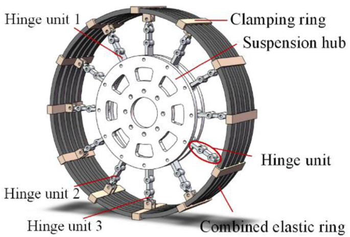
ME-Wheel frame
-
(2)
The suspension hub is installed at the center of the combined elastic rings, and the clamping ring and the suspension hub are connected by the hinge unit.
-
(3)
The combined elastic rings are embedded in the flexible tire body.

2.2 Load Bearing Mode of the ME-Wheel
The wheel has two types of load bearings: bottom load bearing and top load bearing [23, 24]. As no force is exerted on the bottom of the ME-Wheel, the ME-Wheel is top load bearing.
During motion, the ME-Wheel bears not only the uneven road shock excitations but also the vehicle weight and torque from the axle shaft (engine–transmission–axle shaft–wheel). When the ME-Wheel bears the vertical load, the upper part of the wheel hinge unit is under tensile stress from the suspension hub, the lower portion of the wheel hinge unit is in a relaxed state, the lower part of the flexible tire body is deformed, and the hinge unit is gradually bent. The suspension hub is suspended by the hinge unit on the ME-Wheel. This type of load bearing can guarantee the optimal carrying capacity of the flexible tire body, greater deformation contact between the ME-Wheel and the road, and enhanced grip and shock absorbing capacity of the ME-Wheel. When the hinge unit is pulled, it operates as a two-force bar and transfers the axial force. On the other hand, when the hinge unit is pressed, the hinge unit is bent and deformed so that the hinge unit does not bear the force, as shown in Figure 3(a).

ME-Wheel load bearing mode
When the ME-Wheel is subjected to lateral forces, the mechanical connection (hinge unit, clamping ring) of the ME-Wheel will transmit the lateral force to the flexible tire body, which will lead to a certain degree of elastic deformation of the flexible tire body in the grounding area. Compared to the pneumatic tire, the ME-Wheel has greater lateral stiffness, which makes the vehicle equipped with this wheel have better handling stability [25], as shown in Figure 3(b).
3 Interval Mathematical Model of the ME-Wheel Considering Machining and Installation Errors
Interval mathematics is a branch of mathematics that was originally used to solve error problems [26,27,28]. Interval analysis has been widely used in numeral calculations, especially in numerical error analysis.
3.1 Basic Concepts of Interval Mathematics and Interval Arithmetic
Definition: If x1, x2 ∈ R satisfy x1 ≤ x2, then the boundary of the set of real numbers R with a closed interval can be expressed as X = [x1, x2] = {x ∈ R| x1 ≤ X ≤ x2}, where x1 is the lower endpoint of interval X and x2 is the upper endpoint of interval X. If x1 = x2 in interval X, then the interval X is defined as a point interval.
For ∀X = [x1, x2], Y = [y1, y2] ∈ I(R), the four arithmetic I(R) operations are defined as follows:
If interval X = [x1, x2], Y = [y1, y2] ∈ I(R) can satisfy y1 ≤ x1 ≤ x2 ≤ y2, then interval Y contains interval X and is denoted as X ⊆ Y. If intervals X and Y have common components, the two intervals are considered to intersect: X∩Y ≠ Φ and X∩Y is still an interval.
Note that the interval operation satisfies the associative law (X + Y) ± Z = X + (Y ± Z), commutative law X + Y = Y + X, and identity law X + 0 = 0 + X = X, but it does not satisfy the distributive law X (Y + Z) ≠ (XY + XZ); however, its inclusion relationship X (Y + Z) ⊆ XY + XZ satisfies the distributive law.
3.2 Interval Mathematical Model of the ME-Wheel
Figure 4 shows the force and deformation of the wheel perpendicular to the rigid ground without considering the influence of the surface pattern of the ME-Wheel and volume compression of the rubber structural material.

Load deformation of the ME-Wheel
The radius R of the ME-Wheel can be expressed as follows:
where L1, L2, and L3 are the lengths of hinge units 1, 2, and 3, respectively; RC is the radius of the suspension hub; and ∆r is the thickness of the flexible tire body.
As shown in Figure 5, the radial direction of the flexible tire body was selected as the x axis, and then, a polar coordinate system (r, θ, z) was established on the basis of the x axis. The displacements at any point in the coordinate system (r, θ, z) are denoted by (u, v, w).

Radial displacement of the flexible tire body
Therefore, for any point M on the flexible tire body, the radial, tangential, and axial normal strain components εrr, εθθ, εzz are
The shear strain at point M can be expressed as
According to the generalized Hooke’s law, the constitutive equations of the flexible tire body stresses and strains can be expressed as
where GA is the shear modulus of the flexible tire body, EC is the Young’s modulus, and V is the Poisson’s ratio.
Ignoring the axial deformation of the flexible tire body, the volume of any small cell (r, r + dr) can be expressed as
Thus, the normal stress of a plane of length rdθ and width l can be expressed as
The shear stress is
The radial load of the small cell is
Therefore, the radial load of the wheel can be obtained as follows:
Based on Eq. (12), the radial deformation of the flexible tire body can be expressed as follows:
where Fx is the radial force on the flexible tire body, D is the flexible tire body width, r1 is the inner diameter, and r2 is the outer diameter.
The radial stiffness of the flexible tire body can be expressed as follows:
where S is the shape factor [29], AL is the cross-sectional area of the specimen, and AF is the free surface area of the specimen.
The load between the flexible tire body and suspension hub is transmitted by the circumferentially distributed hinge unit. Load analysis of the ME-Wheel shows that the load exerted on the ME-Wheel axle is carried by the extension of all hinge units except the grounded contact area. The ME-Wheel bearing the hinge unit is only subjected to tensile force. Therefore, the hinge unit is simplified (Figure 6) for ease of model analysis.

Hinge unit model
In Figure 6, α = 2π/n, where n is the number of hinge units and t is the thickness of the hinge unit.
In the hinge unit model, the tensile force per unit width of the hinge unit at angle α is
where ED is the Young’s modulus of the hinge unit.
The tension of the ME-Wheel’s hinge unit can be expressed as
where R is the radius of the ME-Wheel, n is the number of hinge units, α = 2π/n, b is the width of the hinges, L is the length of the hinge unit, t is the thickness of the hinge unit, ED is the Young’s modulus, and ur(R) is the radial displacement of the ME-Wheel. The specific data of the ME-Wheel material properties in the formula are presented in Table 1.
Analysis of the ME-Wheel force shows that the radial stiffness of the ME-Wheel is mainly determined by the structural and mechanical properties of the flexible tire body and the hinge unit. The greater the radial stiffness of the flexible tire body, the greater the stiffness of the ME-Wheel. In addition, the rigidity of the flexible tire body depends on the stiffness of the combined elastic rings, number of clamping rings, and size of flexible tire body structure. On the hinge unit, its stiffness also directly affects the overall stiffness of the ME-Wheel.
Since the hinge unit material has the same Young’s modulus during the machining process, in the interval mathematics calculations, one can consider the hinge unit lengths L1, L2, L3, suspension hub radius RC, hinge unit thickness t, and hinge unit width b as the interval number. The main geometric parameters of the ME-Wheel are shown in Table 2.
Considering that the machining errors are approximately ± 1 mm and the installation errors are approximately ± 0.5 mm less than the machining errors, one can determine the error interval as [− 1.5, + 1.5] mm. Therefore, the interval length of the hinge unit is [L − 4.5, L + 4.5] mm, the interval radius of the suspension hub is [RC − 1.5, RC + 1.5] mm, the interval thickness of the hinge unit is [t − 1.5, t + 1.5] mm, and the interval width of the hinge unit is [b − 1.5, b + 1.5] mm.
When the machining and installation errors of the ME-Wheel are in a certain range, the load characteristics of the ME-Wheel are determined by the interval mathematical model, as shown in Figure 7. One can find that the load characteristic curve is weakly nonlinear and the influence of the machining and installation errors on the radial stiffness significantly increases with the wheel load.

Calculation results of the interval mathematical model
4 Interval Finite Element Model of the ME-Wheel
4.1 Finite Element Model of the ME-Wheel
To avoid obtaining an abnormal unit by comprehensive consideration, one can obtain a neat grid by using the hexahedral and sweep method to mesh the model to enhance the convergence and computational accuracy. The stress distribution and deformation of the hinge unit and combined elastic rings are significant in this test; therefore, the mesh of this part is fine and the other parts of the mesh are relatively coarse. At the same time, the tetrahedral mesh method is adopted for the irregular geometry and the size control method is adopted for some important details. Figure 8 shows the FEM of the ME-Wheel with 43424 units and 185474 nodes. In the finite element analysis, material properties must be defined to ensure the finite element analysis results. The material properties of the ME-Wheel in the finite element analysis are given in Table 3.

Finite element model of the ME-Wheel
4.2 Interval Finite Element Model of the ME-Wheel
The interval FEM can be established when the uncertainty factors of the radial stiffness of the ME-Wheel can be expressed by the related parameters whose interval boundary can be defined. The interval finite element calculation formula with an uncertain quantity can be written as follows:
or
where the column vector p is represented as the interval quantity.
The FEM of the ME-Wheel considering the machining and installation errors can be established by the interval finite element method. In contrast to the FEM, the interval FEM is assembled with a shrink fit, as shown in Figure 9. The weak nonlinear relationship shown in Figure 10 is similar to the results in Figure 7.

Interval finite element model of the ME-Wheel

Calculation results of the interval finite element
4.3 Experimental Validation
The radial stiffness experiment of the ME-Wheel was performed on the tire characteristic test bench. The setup and components of the tire characteristic test bench is shown in Figure 11.

Tire characteristic bench test. 1. Roof, 2. Hydraulic cylinders, 3. Platen, 4. ME-Wheel, 5. Floor, 6. Power controller, 7. Side panels, 8. Hydraulic station, 9. Guide post
The loading device of the tire characteristic test bench can provide any radial force to the wheel and maintain a certain load. The loading mode of the platform was designed so that the radial stiffness of the ME-Wheel can be measured accurately.
Data processing for the tire characteristic test bench was performed using Eq. (21),
where F is the elastic force exerted on the wheel, A is the cross-sectional area of the piston plate, \(A\, = \,3.115\, \times \,10^{ - 3}\) m2, and Gb = 1032.43 N is the weight of the platen and the side panels.
For accurate measurements, each radial load was exerted six times on the ME-Wheel with the hinge unit in the ME-Wheel’s six o’clock position and the average value was recorded as the result.
The results of the interval finite element calculation (FEM), the interval mathematical model (analytical model) for the same interval as well as the experimental results are shown in Figure 12.

Load characteristic curve of the ME-Wheel
Figure 12 shows that the load characteristic curve of the wheel is weakly nonlinear, and the influence of the machining and installation errors of the ME-wheel on the radial stiffness increases with the load. In addition, the experimental results for the radial stiffness of the ME-wheel are within the range of the interval mathematical model and interval FEM results. Therefore, the interval mathematical model, interval finite element model, and experimental results for the ME-Wheel have good consistency.
4.4 Influence of the Machining and Installation Errors on the ME-Wheel Radial Stiffness
Radial stiffness is an important factor in wheel vibration. This study mainly focused on the influence of the machining and installation errors on the ME-Wheel radial stiffness, and the length of the hinge unit was used in the parametric analysis.
Four initial radial stiffness values of the flexible tire body—80 N/mm, 100 N/mm, 120 N/mm and 140 N/mm—were calculated by the interval FEM. The interval length of the hinge unit and suspension hub was
In the experiment, the hinge unit length was 192 mm and the suspension hub radius was 220 mm. The ME-Wheel machining and installation errors are shown in Table 4. Figure 13 shows the influence of the machining and installation errors on the ME-Wheel radial stiffness

Influence of machining and installation errors on the radial stiffness of the ME-Wheel
Figure 13(a) shows that the radial stiffness of the flexible tire body significantly influences the ME-Wheel radial stiffness. The maximum difference of the ME-Wheel radial stiffness at the same hinge unit length was more than 100 N/mm. Assuming that the other parameters are unchanged in the given range, the ME-Wheel radial stiffness nonlinearly decreased with increasing hinge unit length. The experimental results were similar to the FEM simulation results on the same horizontal axis value, and both results were within the range of radial stiffness calculated by the interval mathematical model.
Figure 13(b) shows the influence of the suspension hub radius on the radial stiffness of the ME-Wheel. It can be seen that the influence of the hub radius on the radial stiffness is similar to that of the hinge unit length; however, the curves in Figure 13(b) are gentler owing to the smaller interval number range of the suspension hub. The suspension hub radius in the experiment was 220 mm and the experimental value was slightly greater than the simulated value in the same abscissa, and both results satisfied the analysis of the interval mathematical model.
5 Conclusions
-
(1)
The interval mathematical model and interval FEM of the ME-Wheel are both established and validated by bench test, which can provide a reference for the subsequent radial stiffness analysis of the ME-Wheel.
-
(2)
The interval FEM simulation and theoretical calculation can be obtained, the load characteristic curve of the ME-Wheel is weakly nonlinear in a certain range, and the influence of the machining and installation errors on the ME-Wheel radial stiffness increased with the load.
-
(3)
A parametric analysis is conducted at different initial stiffness values of the flexible tire body. The ME-Wheel radial stiffness is found to be inversely proportional to the suspension hub and hinge unit length and the reduction rate of the radial stiffness is greater than the increase in the suspension hub and hinge unit length. In the future, the machining and installation errors can be properly controlled by the regularity of this study, thus the required radial stiffness of the ME-Wheel is obtained.
References
J Ju, B Ananthasayanam, J D Summers, et al. Design of cellular shear bands of a non-pneumatic tire-investigation of contact pressure. Hundred Schools in Arts, 2010, 3(1): 598-606.
L Chen, G Wang, D F An, et al. Tread wear and footprint geometrical characters of truck bus radial tires. Chinese Journal of Mechanical Engineering, 2013, 26(3): 506-511.
Q Liu, A Shalaby. Simulation of pavement response to tire pressure and shape of contact area. Canadian Journal of Civil Engineering, 2013, 40(3): 236-242.
T B Rhyne, R H Thompson, S M Cron, et al. Non-pneumatic tire: US, US 7201194 B2. 2007-04-10.
T B Rhyne, R H Thompson, S M Cron, et al. Non-pneumatic tire having web spokes: US, US 7650919 B2. 2010-01-26.
T B Rhyne, K W Demino, S M Cron. Structurally supported resilient tire: US, US6769465. 2004-08-03.
G M Fadel, J Ju, A Michaelraj, et al. Honeycomb structures for high shear flexure: US, US8651156. 2014-02-18.
J D Summers, G M Fadel, J Ju, et al. Shear compliant hexagonal meso-structures having high shear strength and high shear strain: US, US8609220. 2013-12-17.
D Y Mun, H J Kim, S J Choi. Airless tire: US, US20120060991. 2012-03-15.
C Lee, J Ju, D M Kim. Vibration analysis of non-pneumatic tires with hexagonal lattice spokes. ASME 2012 International Design Engineering Technical Conferences and Computers and Information in Engineering Conference, Chicago, Illinois, USA, August 12–15, 2012: 483–490.
M Veeramurthy, J Ju, L L Thompson, et al. Optimization of a non-pneumatic tire for reduced rolling resistance. ASME 2011 International Design Engineering Technical Conferences and Computers and Information in Engineering Conference, Washington, DC, USA, August 28–31, 2011: 861–868.
Y Q Zhao, L G Zang, Y Q Chen, et al. Non-pneumatic mechanical elastic wheel natural dynamic characteristics and influencing factors. Journal of Central South University, 2015, 22(5): 1707-1715.
W Wang, Y Q Zhao, L G Zang, et al. Structure analysis and ride comfort of vehicle on new mechanical elastic tire. Proceedings of the FISITA 2012 World Automotive Congress, Beijing, China, November 27, 2013: 199–209.
Q Wang, Y Q Zhao, X B Du, et al. Equivalent stiffness and dynamic response of new mechanical elastic wheel. Journal of Vibroengineering, 2016, 18(1): 431-445.
L G Zang, Y Q Zhao, C Jiang, et al. Mechanical elastic wheel’s radial stiffness characteristics and their influencing factors. Journal of Vibration and Shock, 2015, 34(8): 181–186. (in Chinese)
L G Zang, Y Q Zhao, B Li, et al. Static radical stiffness characteristics of non-pneumatic mechanical elastic wheel. Acta Armamentarii, 2015, 36(2): 355-362. (in Chinese)
L G Zang, Y Q Zhao, B Li, et al. An experimental study on the ground contact characteristics of non-pneumatic mechanical elastic wheel. Automotive Engineering, 2016, 38(3): 350-355. (in Chinese)
B Li, Y Q Zhao, L G Zang. Closed-form solution of curved beam model of elastic mechanical wheel. Journal of Vibroengineering, 2014, 16(8): 3951-3962.
X B Du, Y Q Zhao, Q Wang, et al. Numerical analysis of the dynamic interaction between a non-pneumatic mechanical elastic wheel and soil containing an obstacle. Part D: Journal of Automobile Engineering, 2017, 231(6): 731-742.
A N Gent, J D Walter, Y T Wei, et al. The pneumatic tire. Beijing: Tsinghua University Press, 2013. (in Chinese)
Z W Wang, Q J Yang, G Bao, et al. Effect of manufacturing errors on static characteristics of externally pressurized spherical air bearings. Chinese Journal of Mechanical Engineering, 2009, 22(6): 896-902.
X H Han, L Hua, D Song, et al. Influence of alignment errors on contact pressure during straight bevel gear meshing process. Chinese Journal of Mechanical Engineering, 2015, 28(6): 1089-1099.
T B Rhyne. Influence of rim run-out on the nonuniformity of tire-wheel assemblies. Tire Science and Technology, 1994, 22(2): 99-120.
T B Rhyne, S M Cron. Development of a non-pneumatic wheel. Tire Science and Technology, 2006, 34(3): 222-225.
H X Fu, Y Q Zhao, F Lin, et al. Theoretical and experimental analysis on steady-state cornering properties of mechanical elastic wheel. Journal of Zhejiang University (Engineering Science), 2017, 51(2): 1-6. (in Chinese)
G Alefeld, J Herzberger. Introduction to interval computation. New York: Academic Press, 1983.
R E Moore. Methods and applications of interval analysis. Philadelphia: Society for Industrial and Applied Mathematics, 1995.
P Thieler. Technical calculations by means of interval mathematics. Interval Mathemantics 1985: Proceedings of the International Symposium, Freiburg I. Br. Federal Republic of Germany, September, 1986: 197–208
H Tohara, C W Mu. Anti-vibration rubber and its application. Beijing: China Railway Publishing House, 1982. (in Chinese)
Authors’ Contributions
ZX and FL was in charge of the whole trial; Y-QZ and ZX wrote the manuscript; M-MZ and Y-JD assisted with sampling and laboratory analyses. All authors read and approved the final manuscript.
Authors’ Information
You-Qun Zhao, born in 1968, is a professor at Nanjing University of Aeronautics and Astronautics, China. His research interests include vehicle dynamics control and automotive design theory and test methods, etc.
Zhen Xiao, born in 1989, is a PhD candidate at Nanjing University of Aeronautics and Astronautics, China. His research interests include vehicle dynamics control and tire dynamics.
Fen Lin, born in 1980, is currently an associate professor at Nanjing University of Aeronautics and Astronautics, China. He received his PhD degree from Nanjing University of Aeronautics and Astronautics, China, in 2008. His research interest is vehicle system dynamics.
Ming-Min Zhu, born in 1986, is a PhD candidate at Nanjing University of Aeronautics and Astronautics, China. Her research interests include vehicle dynamics control and tire dynamics.
Yao-Ji Deng, born in 1991, is a PhD candidate at Nanjing University of Aeronautics and Astronautics, China. His research interests include vehicle dynamics control and tire dynamics.
Competing Interests
The authors declare that they have no competing interests.
Funding
Supported by National Natural Science Foundation of China (Grant No. 11672127), Major Exploration Project of the General Armaments Department of China (Grant No. NHA13002), Fundamental Research Funds for the Central Universities of China (Grant No. NP2016412, NP2018403, NT2018002), and Jiangsu Provincial Innovation Program for Graduate Education and the Fundamental Research Funds for the Central Universities of China (Grant No. KYLX16_0330).
Publisher’s Note
Springer Nature remains neutral with regard to jurisdictional claims in published maps and institutional affiliations.
Author information
Authors and Affiliations
Corresponding author
Rights and permissions
Open Access This article is distributed under the terms of the Creative Commons Attribution 4.0 International License (http://creativecommons.org/licenses/by/4.0/), which permits unrestricted use, distribution, and reproduction in any medium, provided you give appropriate credit to the original author(s) and the source, provide a link to the Creative Commons license, and indicate if changes were made.
About this article

Cite this article
Zhao, YQ., Xiao, Z., Lin, F. et al. Influence Analysis of Machining and Installation Errors on the Radial Stiffness of a Non-Pneumatic Mechanical Elastic Wheel. Chin. J. Mech. Eng. 31, 68 (2018). https://doi.org/10.1186/s10033-018-0273-y
Received:
Accepted:
Published:
DOI: https://doi.org/10.1186/s10033-018-0273-y