- Original Article
- Open access
- Published:
Optimal Design of Novel Electromagnetic-Ring Active Balancing Actuator with Radial Excitation
Chinese Journal of Mechanical Engineering volume 34, Article number: 9 (2021)
Abstract
Imbalance vibration is a typical failure mode of rotational machines and has significant negative effects on the efficiency, accuracy, and service life of equipment. To automatically reduce the imbalance vibration during the operational process, different types of active balancing actuators have been designed and widely applied in actual production. However, the existing electromagnetic-ring active balancing actuator is designed based on an axial excitation structure which can cause structural instability and has low electromagnetic driving efficiency. In this paper, a novel radial excitation structure and the working principle of an electromagnetic-ring active balancing actuator with a combined driving strategy are presented in detail. Then, based on a finite element model, the performance parameters of the actuator are analyzed, and reasonable design parameters are obtained. Self-locking torque measurements and comparative static and dynamic experiments are performed to validate the self-locking torque and driving efficiency of the actuator. The results indicate that this novel active balancing actuator has sufficient self-locking torque, achieves normal step rotation at 2000 r/min, and reduces the driving voltage by 12.5%. The proposed novel balancing actuator using radial excitation and a combination of permanent magnets and soft-iron blocks has improved electromagnetic efficiency and a more stable and compact structure.
1 Introduction
Rotational machines, including turbine machinery [1, 2] and machine tools [3, 4], are extensively employed in industrial production. Rotary machines have become quite large, complex, and automated [5]. Imbalance vibration, a typical failure mode of rotational machines, is caused by imbalanced mass distribution and has a significant negative effect on the efficiency, accuracy, and service life of the equipment. Dynamic balancing technology includes process balancing [6], on-site balancing [7, 8], and active balancing [9,10,11,12,13]. Process dynamic balancing requires the use of a balancing machine, which is time consuming, laborious, and cannot readily ensure balance accuracy. On-site dynamic balancing can achieve dynamic balancing during the actual working state of the rotor and reduces the imbalance to a relatively low level, but requires field operation. Active balancing actuators [14], which are designed to automatically reduce imbalance vibration during the operational process without halting the machine or human intervention, are considered an effective solution to imbalance vibration in rotary machines.
In the past few years, multiple types of active balancing actuators have been developed. Based on the methods of changing the mass distribution, balancing actuators can be categorized as mechanical [15], liquid [16,17,18], magnetic-bearing [19,20,21,22], and electromagnetic-ring types [23,24,25]. The mechanical balancing actuator has been successfully applied owing to its convenience, but its service life is restricted by mechanical wear. A liquid-type balancing actuator provides a compensated mass by pumping an oil-water mixture into several sector cavities, but suffers from two flaws: It is difficult to eject the mixture when the cavities are full, and the balance state is not maintained after machine halting [26, 27]. Compared to the above two kinds of actuators, electromagnetic-ring balancing actuators, which use electromagnetic force to drive the counterweight block for dynamic balancing, have the advantages of small volume, rapid response, high accuracy, and easy assembly. This type of balancing actuator does not require a complex auxiliary system and is easy to operate. Moreover, the control signal does not need to be transmitted between the moving and static parts, which means that the actuator completely avoids the need for parts which can wear out, such as electric brushes [28, 29]. Therefore, the active balancing actuator has a long equipment life. However, the moving and static parts of traditional electromagnetic-ring balancing actuators need to be installed separately. The gap between the rotating and non-rotating parts should be less than 0.5 mm, which makes the installation difficult. Integrative electromagnetic-ring balancing actuators solve these problems to a certain degree [30]. For example, the gap between the moving and static parts does not require adjustment during installation. Nevertheless, because of the axial excitation structure, the counterweight disc may be drawn to the other component of the actuator, which causes severe disruptions to the balancing process. Thus, an electromagnetic-ring balancing actuator that adopts a radial excitation structure is proposed in this paper. This novel type actuator effectively avoids the deflection and friction associated with the counterweight disc and has significantly improved efficiency and stability.
The principle of the balancing and radial excitation, and the basic structure of the novel actuator are described in Section 2. The parameters of the actuator, such as the self-lock and the driving torques, are analyzed by electromagnetic simulations, and the advantages of the new actuator are explained in Section 3. The static and dynamic experiments to validate the operating performance of the actuator are described in Section 4.
2 Principle of the Radial Excitation Actuator
2.1 Balancing Principle
The core components of the actuator are two symmetrical counterweight discs, as shown in Figure 1(a). Each disc provides a semi-circular counterweight block to form an eccentric mass U. Because the two blocks A and B have the same shape and material, the eccentric masses UA and UB are equal, and the total compensation mass UC is zero when these two blocks are oriented in opposite directions. When the actuator is activated to balance the initial imbalance mass U0 of the rotor, the two discs start to rotate in a stepwise manner under the action of an electromagnetic force, thereby changing the included angle between the masses UA and UB. Based on the parallelogram rule, the total compensation mass UC increases gradually as the included angle decreases. When the blocks are oriented in the same direction and the included angle is zero, the total mass UC reaches its maximal value, which is the sum of UA and UB. The initial imbalance mass U0 of the rotor can be balanced from 0 to the maximal value of UC by adjusting the angles φ and φc.

Basic principle of the actuator: a Core components; b Schematic diagram.
The residual imbalance mass UR of the rotor is given by
The compensation mass is determined by the included angle φ, that is,
where UAB is the eccentric mass of each disc.
Because the counterweight discs rotate in a stepwise manner during operation, the compensation mass can be written as
where Δφ is the angle step size and j is the step of the compensation mass. The compensation mass when UAB is 5000 g·mm and φ varies from 0° to 90° with a step size of 7.5° is shown in Figure 2.

Variation of the compensation mass with the included angle.
2.2 Radial Excitation Principle
The radial excitation structure, including the counterweight disc and inner/outer excitation ring, is the core component of the actuator, as shown in Figure 3. A convex ring that extends into the gap between the teeth of the inner and outer excitation rings is positioned on the circumference of the counterweight disc. The teeth of the inner excitation rings, the permanent magnets/soft-iron blocks, and the teeth of the outer excitation rings are arranged radially from the inside out. The magnetic field passes through the permanent magnets/soft-iron blocks along the radial direction, and only radial electromagnetic forces are generated between the excitation rings and the counterweight disc. Therefore, this excitation is called radial excitation.

Radial excitation structure: a Counterweight disc; b Inner/outer excitation ring.
2.2.1 Design of the Magnetic Circuit
To drive the stepwise rotation of the counterweight discs using an electromagnetic force, a closed magnetic circuit is required for each disc to generate the electromagnetic field. Because of the axisymmetric structure of the proposed actuator, only one-quarter of the structure is taken for the magnetic circuit analysis in Figure 4. The center stator, coil cases, and inner/outer excitation rings are all made of a magnetic conductive material, such as electrical pure iron DT4E, and all of them constitute the closed magnetic circuit.

Magnetic circuit diagram.
When the balancing actuator is activated, the coil creates a magnetic field, which magnetizes the coil case. The magnetic induction lines pass through the air gap δ1 between the coil case and excitation rings. Then, the magnetic field magnetizes the inner and outer excitation rings through the air gap δ2, and north and south poles are formed on the iron teeth of the inner and outer excitation rings, respectively. According to the “like-wise repulsion, opposite-between attraction” principle of magnetic poles, the iron teeth in both excitation rings interact with the permanent magnets and soft-iron blocks mounted on the counterweight discs and drive the counterweight discs to rotate in steps relative to the excitation rings. Ultimately, the magnetic induction line is transferred back to the coil case through the air gap δ3, the center rotator, and the air gap δ4 to close the magnetic circuit.
2.2.2 Self-locking of the Counterweight Disc by Permanent Magnets
The excitation can be performed in the actuator only when the unbalanced vibration of the rotor exceeds the standard and the self-locking condition without external excitation is satisfied. This ensures that the rotation between the counterweight discs and the rotating part is synchronized without a change in the mass distribution when the actuator accelerates, decelerates, and rotates constantly.
As shown in Figure 5(a), when the counterweight disc is in the self-locking condition, each adjacent pair of permanent magnets corresponds to a tooth on the inner and outer excitation rings, and the mating area of each magnet is approximately half of its own area. Therefore, the self-locking force between each pair of permanent magnets and the inner and outer rings is equivalent to the attraction force between a permanent magnet and a soft-iron block. When the ratio of the air gap δ2 to the permanent magnet radius Rg is within 1.0, that is, δ2/Rg≤1.0, the attraction force Fg is given by
where Ag is the effective pole area of the magnet, Bg is the magnetic density produced by the magnet at the air gap, and μ0 is the magnetic conductivity at the air gap and is equal to a constant.

Analysis diagram of the self-locking condition: a Axial view; b Force analysis.
The magnetic density Bg can be written as
where Br is the remanence intensity of the magnet.
Denoting the number of permanent magnets as K and the installation radius of the magnets as R, the total self-locking torque of the counterweight disc is given by
The specific parameters of the permanent magnets in the actuator are listed in Table 1. The self-locking torque when the air gap δ2 is varied from 0.2 mm to 2.0 mm is shown in Figure 6. Based on the analysis results, the following conclusions can be drawn: (1) the self-locking torque decreases rapidly with increasing air gap δ2, and (2) the self-locking torque is proportional to the number of magnets. Therefore, the number of magnets needed to obtain a given self-locking torque can be greatly reduced if the air gap δ2 is decreased. For example, if the required self-locking torque is 500 mN·m, twelve magnets are needed with an air gap of 1.6 mm, whereas only four magnets are needed with an air gap of 0.3 mm.

Theoretical self-locking torque.
2.2.3 Principle of Driving by Magnets and Soft-Iron Blocks
The air gap δ2 is greatly reduced is an actuator with radial excitation. It is therefore no longer necessary to install as many magnets on the convex ring of the counterweight disc. A soft-iron block can be placed in the remaining circumferential space to provide the driving force and improve the driving ability of the actuator.
The force acting on a conducting material in a magnetic field can be expressed as
where χ, ρ, and V are the magnetization coefficient, density, and volume of the material, respectively, while H and dH/dx are the intensity and gradient of the magnetic field, respectively.
The magnets and soft-iron blocks on the counterweight disc experience the same magnetic field and have the same material volume. There is a very small difference between the respective densities of 7.45 g/cm3 and 7.8 g/cm3 in the two materials. Accordingly, the driving force during the working process is determined mainly by the magnetic coefficients of the two materials. To compare the magnetic difference between the two materials, an experiment was performed. The results show that in the same magnetic field, the force from a magnet with a given volume is approximately three times that of a soft-iron block with the same volume. Therefore, if only 8 magnets are needed for the counterweight disc to meet the self-locking force requirements and the number of soft-iron blocks is 3 times the number of magnets, i.e., 24, the driving force of the counterweight disc can be doubled, as shown in Figure 7.

Working process of the actuator: a Start-up position; b Middle position; c Stop position.
During self-locking, only the magnets can be used to produce self-locking torques; the soft-iron blocks do not contribute. When the coil is powered by a power supply, the two excitation rings are magnetized immediately. As shown in Figure 7(a), the electromagnetic force generated between the magnets and excitation rings drives the counterweight disc to rotate in steps relative to the rotor. The electromagnetic force between the soft-iron blocks and excitation rings cannot drive the counterweight disc in the start-up position, but when the counterweight disc deviates from its initial position, the soft-iron blocks start to drive the counterweight disc in the same direction as the magnets.
When the coil current is cut off at the middle of each step as shown in Figure 7(b), the electromagnetic field generated by the coil disappears instantaneously, and the driving torque provided by the permanent magnets and soft-iron blocks decreases quickly to 0. The inertia of the counterweight disc and the self-locking torque causes the counterweight disc to continue to pass through the middle position of each step and slow down gradually. Ultimately, as shown in Figure 7(c), the counterweight disc reaches the stop position and returns to the self-locking condition again.
2.2.4 Comparison with Traditional Excitation
Compared with the traditional axial excitation structure, the radial excitation structure has two obvious differences, namely, the radial excitation direction and the driving principle of the permanent magnets and the soft-iron blocks, as shown in Figure 8. The novel structure has the following advantages: (1) The counterweight disc no longer bears an axial force, which essentially avoids the problems of deflection and friction with the excitation rings and increases the stability and reliability of the device during operation. (2) The air gap between the counterweight disc and excitation rings is narrowed, and the self-locking torque can be obtained with fewer magnets. (3) In addition to magnets, soft iron blocks are used to provide the driving torque, which can greatly improve the driving efficiency of the actuator and reduce the driving voltage demand.

Structural comparison: a Traditional axial excitation; b Novel radial excitation.
2.3 Basic Structure
The basic structure model of the actuator based on the principles of balancing and radial excitation is shown in Figure 9. The part that rotates synchronously with the rotor includes the actuator case, two inner excitation rings, two outer excitation rings, two counterweight discs, and a pair of rotatory-ring bearings, which are distributed symmetrically inside the actuator case. Specifically, the inner excitation rings are fixed to both sides of the center partition of the actuator case with bolts, and the outer excitation rings are installed on the inner surface of the actuator case. There are several iron teeth machined on the outer circle of the inner excitation ring and the inner circle of the outer excitation ring, and there is a one-to-one correspondence of the teeth in the radial direction. Counterweight discs with counterweight blocks are connected to the inner excitation rings by rotatory-ring bearings. The magnetic circuit of the rotating part was discussed in Section 2.2.

Actuator structure: a Overall model; b Rotating part; c Non-rotating part; d Detailed structure.
The non-rotating part comprises a center stator, two coils with coil cases, a stationary-ring shell, and an aviation connector frame. The center stator, which is a symmetrical stepped shaft, is machined with a through hole in its radial direction to position the wires of two coils. A pair of coils is installed inside each coil case. Additionally, two through holes are placed at the bottom of each coil case to lead the coil wire out. A stationary-ring shell is installed outside of each coil case, and an aviation connector frame is installed under the stationary-ring shell to prevent the stationary part from rotating during operation and to collect all the wires of the actuator.
During operation, the rotating part corrects the imbalance by compensating the mass, while the non-rotating part receives electric pulses from the power supply. The rotating and non-rotating parts are connected by a pair of connecting bearings, which guarantees the long-term operation of the balancing actuator.
3 Optimized Design
The key parameters of the actuator are listed in Table 2. The parameters to be optimized and their value ranges are indicated in bold. The Maxwell software was used to analyze the electromagnetic characteristics of the actuator. Through electromagnetic simulations, the magnetic field and the magnetic induction lines of the actuator can be observed, and the initial parameter analysis results (such as the self-locking torque and the driving torque) can be obtained. These results will inform the series of balancing actuator performance experiments described in Section 4.
3.1 Self-locking Torque
As stated above, the actuator usually operates in the self-locking condition. The self-locking torque generated by the magnets and excitation rings ensures the synchronous rotation of counterweight discs when no actuator step rotation is required for the actuator. Therefore, to ensure that the magnetic force can provide sufficient self-locking torque for the counterweight disc, the magnetic force of the structure in the non-excitation state should be analyzed through simulation.
A 3D model of the actuator was created with SolidWorks and then imported into Maxwell, as shown in Figure 10(a). Because of the symmetry of the actuator, only half of the structure was imported, and irrelevant parts such as the actuator case, counterweight blocks, coils, coil cases, and ball bearings were removed. Then, a finite element model of the actuator was established, as shown in Figure 10(b). The material properties of each part of the actuator were set as shown in Table 3. The magnetizing direction of each magnet was along the radial direction of the counterweight disc, and the magnetizing directions of adjacent magnets were opposite to each other.

Self-locking simulation: a 3D model; b Finite element model; c Axial section; d Circumferential section.
An area with a padding percentage of 200% was created outside the model as the calculation area. Considering that the magnetizing direction of the permanent magnets changed constantly during the rotation of the counterweight disc, the magnetizing direction of each permanent magnet was set as a variable. The alternative of setting the rotation angle of the counterweight disc around the actuator axis as a variable would complicate the analysis process. Using the principle of relative motion, the counterweight disc was considered as the reference, and the rotation angle of the inner-outer excitation rings around the axis was set to the variable x1. The same results were obtained when this greatly simplified analysis process was implemented. Considering the interval between the adjacent magnets and soft-iron blocks of approximately 7.5°, the value of variable x1 was set to 0–15°, and the step length was set to 0.5°.
The axial torque on the counterweight produced by the disc magnets and soft-iron blocks was taken as the executive parameter. The analysis setup was created with the maximum number of passes set to 20, the percentage error set to 1%, and the refinement per pass set to 30%. The calculation was completed using the “Validate check” and “Analyze all” processes, and the distribution of the magnetic induction lines and magnetic field intensity in the entire structure obtained are shown in Figure 10(c). To visualize the magnetic field distribution between the permanent magnets and the iron teeth of the excitation rings, a section was created at the magnets along the radial direction of the actuator. The magnetic field of the section between the magnets and the mating parts are displayed using a magnetic field distribution cloud map, as shown in Figure 10(d).
The variation of the calculated self-locking torque with the rotation angle of the counterweight disc was calculated. Three conclusions can be drawn from the results:
-
1)
The self-locking torque varies periodically every 7.5°, which is the interval between the adjacent magnets or soft-iron blocks on the counterweight disc, as shown in Figure 11(a). During the step rotation of the counterweight disc, the self-locking torque reaches its maximum value at 1/4 and 3/4 step. The front and back half steps have opposite torque directions in which the self-locking torque of the front half step prevents the stepwise motion of the counterweight disc and the self-locking torque of the back half step drives the step of the counterweight disc. When the permanent magnet material is N35, the air gap δ2 is 0.6 mm, and the number of permanent magnets is 12, the maximum value of the self-locking torque is approximately 728.5 mN·m.
Figure 11 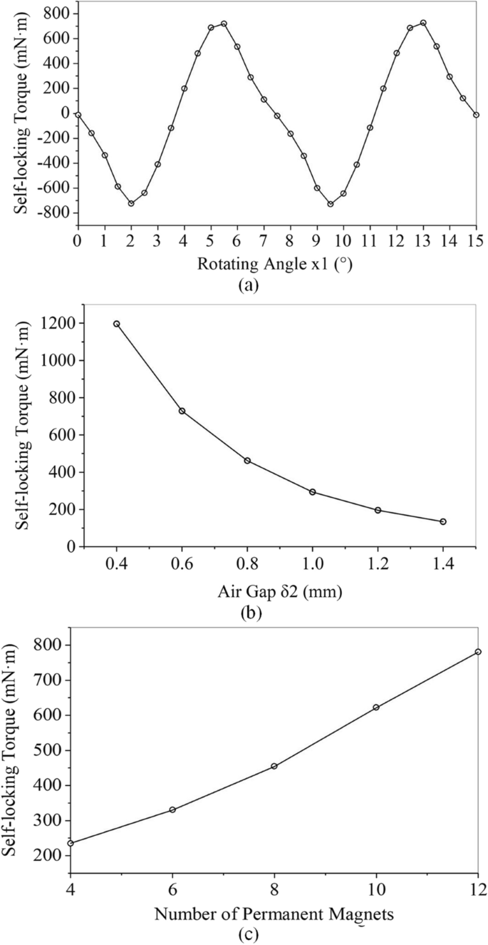
Simulation results for variation of self-locking torque with: a Rotating angle; b Air gap; c Number of magnets.
-
2)
The maximum value of the self-locking torque in each step increases with the reduction of the air gap δ2, as shown in Figure 11(b). This trend is essentially the same as that in Figure 6 in Section 2.2. The error increases with the size of the air gap mainly because of magnetic flux leakage, magnet size error, and the force angle.
-
3)
The greater the number of permanent magnets, the larger is the self-locking torque. The maximum value of this torque is proportional to the number of permanent magnets on the counterweight disc, which is confirmed by both Equation 6 and Figure 11(c).

3.2 Driving Torque
The step rotation of the counterweight disc is mainly affected by the driving torque. Consequently, in this section, the variations in the electromagnetic force between the inner-outer excitation rings and the permanent magnets after excitation are analyzed through simulations.
As shown in Figure 12, a half structure of the actuator was imported into Maxwell for finite element analysis. The half structure included the inner-outer excitation rings, counterweight disc, center stator, coils, and coil cases. The material of the coil case was set to DT4C, that of the coil to copper, and the material properties of the remaining parts were similar to those in the self-locking torque analysis model. The excitation current loading surface was created in the radial direction of the coil, and the direction of the excitation current was as shown in Figure 12(b). According to the principle of relative motion, the counterweight disc was set as the reference, and the rotation angle of the inner-outer excitation rings around the axis was set as the variable x2. Considering that the variation period of the driving torque is approximately 15°, the value range of the variable x2 was set to 0–20° with a step size of 0.5°. The axial torque on the counterweight disc was again taken as the executive parameter. The analysis setup was created with the following settings: the maximum number of passes was set to 20, the percentage error was set to 1%, and the refinement per pass was set to 30%. After the model was confirmed, “Validate check” and “Analyze all” were clicked on to calculate the global finite element model of the actuator. Sections along the radius and axis of the actuator were created to obtain the cloud maps of the magnetic field shown in Figure 12(c) and (d).

Driving simulation: a Finite element model; b Current loading surface; c Circumferential section; d Axial section.
When the radial excitation mode is applied, the driving torque can remain unchanged or even increase with increasing magnetic force, and the self-locking torque can be compensated at the same time. To confirm this, the contribution of different numbers of soft-iron blocks to the driving torque was analyzed after replacing the magnets with soft-iron blocks on the counterweight disc. The specific manner in which the number of soft-iron blocks on the counterweight disc was changed is shown in Figure 13 (the grey blocks are the soft-iron blocks).

Contribution of soft-iron blocks: a 0 soft-iron blocks; b 8 soft-iron blocks; c 16 soft-iron blocks; d 24 soft-iron blocks.
The air gap δ1 was set to 0.5 mm and the number of soft-iron blocks on the counterweight disc set to 0, 8, 16, and 24 to analyze the variation of the actual driving torque with the number of soft-iron blocks. The results are shown in Figure 14(a). The driving torque of the actuator increases with the number of soft-iron blocks on the counterweight disc. This proves that the iron can effectively provide the torque for the disc.

Simulation results of driving torque: variation of torque with a Number of soft-iron blocks; b Air gap; and c Rotating angle.
The air gap δ1 between the rotating and non-rotating parts was varied with the number of soft-iron blocks on the counterweight disc set to 24, and the resulting actual driving torque was analyzed. The results obtained are shown in Figure 14(b). As the air gap δ1 gradually increases, the driving torque of the actuator decreases. To obtain the greatest possible torque, the gap δ1 should be minimized.
As described above, the actual driving torque is the vector sum of the theoretical driving torque and the self-locking torque. The relationship between these three torques when there are 24 soft-iron blocks on the counterweight disc is analyzed. As shown in Figure 14(c), the variational period of the driving torque is 7.5°. When the coil is powered up, an electromagnetic torque is generated to drive the rotation of the counterweight disc. The driving torque increases to a maximum and subsequently decreases to zero rapidly at the 1/2 step position. If the coil is not powered off in time, a reverse electromagnetic driving torque will be generated. Therefore, before the counterweight disc reaches the 1/2 step position, it is necessary to cut off the excitation current and let the disc pass through this position by inertia. Subsequently, the self-locking torque serves as the driving torque and continues to drive the counterweight disc to complete the rotation step.
4 Experiments
The prototypical actuator shown in Figure 15 was used to perform the self-locking torque measurement and the static/dynamic experiment of the actuator. The total length of the actuator was 108 mm, the maximum diameter was 130 mm, and the balancing ability of the counterweight blocks was more than 12000 g·mm. The counterweight disc can be configured with a maximum of 32 removable soft-iron blocks. The side of the actuator near the flange of the case is named the Side A, and the other side is named the B side.

Prototype of the actuator: a Actuator components; b Self-locking torque measurement of the actuator.
4.1 Self-locking Torque Measurement
A long length scale and weight were used to measure the self-locking torque of the actuator, as shown in Figure 15(b). The coil case and its coil on side B of the actuator were removed to expose the counterweight disc, and the long scale was affixed to the counterweight disc through horizontal holes. The weight was hung on the side of the scale, and its position was adjusted until the counterweight disc rotated. The scale reading of the location of the weight was recorded and multiplied by the weight to obtain the self-locking torque on one side. Then, the weight was hung on the other side of the scale, and the above procedures were repeated to obtain the self-locking torque in the other direction. The actuator case was rotated by one step to obtain the forward and reverse self-locking torques in the next step. We repeated the above procedures to obtain the forward and reverse self-locking torques of the counterweight disc for a total of 48 steps. The number of permanent magnets used in the experiment was 12, and the experimental results are shown in Figure 16(a). The self-locking torque changes periodically with the rotating step and is mainly influenced by the gravitational force acting on the counterweight. The maximum values on both sides are 0.79 N·m.

Experimental results for variation of self-locking torque with: a Rotating angle; and b Number of magnets.
To confirm the relationship between the self-locking torque and the number of magnets, the number of permanent magnets on the counterweight disc was varied between 4 to 12. The latter is the number used to measure the average value of the self-locking torque in each group. The experimental results are shown in Figure 16(b). Similar to the simulation results in Figure 11(c), the self-locking torque of the actuator increases with the number of permanent magnets from approximately 0.2 N·m to 0.8 N·m. This result verifies the effectiveness of the actuator self-locking function.
4.2 Static Experiments
To verify the effectiveness of the driving torque, the minimum driving voltage required for the step rotation of the actuator under static conditions was measured. This voltage can also be considered as the minimum coil excitation voltage required for the counterweight disc to complete a full-circle step rotation. The experimental setup is shown in Figure 17. Each step was marked with a different color on the outer circle of the counterweight disc so that the step rotation state of the counterweight disc could be observed by an endoscope placed through the through hole in the actuator case. A DC power supply was connected to a controller equipped with a timing device to control the pulse width of the output voltage. A reversing switch was also connected in series in the circuit to change the direction of the output voltage and apply positive and negative pulses to the coil to realize the full-circle step rotation of the counterweight disc.

Static condition experimental setup.
The following two conclusions are obtained from the experimental results:
-
1)
The minimum driving torque of the actuator was measured using counterweight discs equipped with 0, 8, 16, and 24 soft-iron blocks. The experimental results are shown in Figure 18(a). A comparison of the experimental and simulation results shows that when the number of soft-iron blocks increases, the driving torque of the actuator increases, and the minimum driving voltage decreases correspondingly. When the number of soft-iron blocks increases, the minimum driving voltage decreases from approximately 84 V to 73.5 V. Compared to the case without soft-iron blocks, the counterweight disc with 24 soft-iron blocks reduces the minimum driving voltage by 12.5%. This result verifies the effectiveness of the radial excitation and the soft-iron blocks.
Figure 18 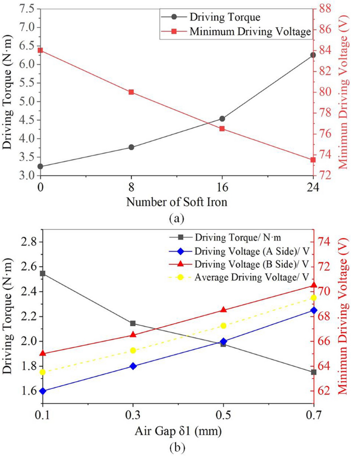
Results of static experiments: variation of driving torque with: a Number of soft-iron blocks; and b Air gap.
-
2)
The air gap δ1 was changed by installing gaskets between the non-rotating and the rotating parts while the numbers of magnets and soft-iron blocks were fixed at 12 and 24 respectively and δ2 was fixed at 0.6 mm. The relationship between the minimum driving voltage on both sides and the air gap δ1 is shown in Figure 18(b). A comparison of the experimental results with the simulation results in Section 3.2 shows that when the air gap δ1 increases, the actuator driving torque decreases, and the minimum driving voltage increases correspondingly. When the air gap δ1 is increased by 0.2 mm, the driving voltage of both sides needs to increase by approximately 2 V. It is confirmed that the radial excitation is effective under the static condition and that the air gap needs to be minimized to improve the electromagnetic efficiency of the actuator.

4.3 Dynamic Experiments
The actuator was installed at the end of the rotor of a grinding machine through a flange connection. We tested the step rotation of the actuator with the rotor rotating and determined the minimum driving voltage of the actuator at several rotation speeds. The experimental setup is shown in Figure 19. The frequency converter controls the rotating speed of the rotor to realize variable-speed rotation of the actuator. The coil is connected to the power supply, and the pulse width of the output pulse is controlled by the controller. Because the endoscope cannot be used to observe the step rotation state of the counterweight disc when the grinding machine is rotating, phase sensors are required to monitor the phase of the counterweight disc. In this experiment, a reference magnet was installed in the actuator case, two locating magnets A and B were installed on the counterweight disc, and two sets of Hall sensors were installed at the corresponding positions of the non-rotating part to monitor the phase of the counterweight disc. The output signal of each Hall sensor was sent to the analog signal input board of the NI data acquisition equipment. The data acquisition equipment was connected to a computer through an Ethernet cable.

Experimental setup of the dynamic experiment
A LabVIEW program was used to process the output signal of the Hall elements to obtain the instantaneous phase signals of the counterweight disc. The phase change in the counterweight disc was recorded in a phase-time chart on the front panel of the LabVIEW program, as shown in Figure 20(a).

Phase monitoring of the counterweight disc: a LabVIEW program; b Phase-time chart.
Positive and negative pulse excitations were applied to the excitation coil. If the counterweight disc could rotate smoothly, the phase would be continuously changed in the same direction by 360° in a ladder shape. The results in Figure 20(b) show that the actuator can achieve normal step rotation at the rotating speeds of 1000 r/min, 1500 r/min, and 2000 r/min.
If the counterweight disc failed to rotate continuously, the outcome will be displayed as a reverse phase change. Based on this method, the minimum driving voltage of the counterweight disc at a given speed could be determined. In the experiment, a counterweight disc with 12 magnets and 24 soft-iron blocks was used. The coils on both sides, A and B, were installed at the same time. The experimental results are shown in Figure 21.

Demand for driving voltage at several rotating speeds
In the figure, the black and red curves correspond to the variation of the minimum driving voltage of the A and B counterweight discs with the rotating speed of the rotor, respectively. Because of machining and installation errors, the values for Side A are approximately 2 V higher than that for Side B, and both sides exhibit similar trends. The experimental results show that the minimum driving voltage of the actuator increases with the rotating speed, and the driving voltage is less than 70 V when the rotating speed is less than 2000 r/min.
5 Conclusions
A novel active balancing actuator with radial excitation was proposed in this paper.
-
(1)
The basic structure and working principle of the actuator were introduced and two major features were emphasized, namely, the radial excitation structure and the combination of permanent magnets and soft-iron blocks. Through comparison with similar existing structures, the novel structure was shown to effectively improve the electromagnetic efficiency, stability, and compactness of the actuator.
-
(2)
The Maxwell software was used to simulate the electromagnetic characteristics of the actuator. The simulation results show that the self-locking torque of the actuator increases with a reduction in the air gap and that the actuator can achieve self-locking with fewer magnets. The driving torque of the actuator increases with the placement of additional soft-iron blocks on the counterweight disc. This proves that the iron can effectively provide the torque for the disc.
-
(3)
Self-locking torque measurements and static and dynamic experiments were performed to verify the effectiveness of the actuator. The experimental results show that the novel actuator can achieve normal step rotation at 2 000 r/min, and that the driving voltage is reduced by 12.5% by adding 24 soft-iron blocks to the counterweight disc.
References
D Zappala, N Sarma, S Djurovic, et al. Electrical & mechanical diagnostic indicators of wind turbine induction generator rotor faults. Renewable Energy, 2019, 131: 14-24.
Y Kaneko, H Kanki, R Kawashita. Steam turbine rotor design and rotor dynamics analysis. Advances in Steam Turbines for Modern Power Plants, Woodhead Publishing, 2017: 127-151.
S P Chen, Z Z Wang, H Yu, et al. Research on automatic compensation technology for eccentricity of grinding wheel. International Journal of Precision Engineering and Manufacturing, 2018, 19(8): 1201-1209.
M Rezaee, R Fathi. A new design for automatic ball balancer to improve its performance. Mechanism and Machine Theory, 2015, 94: 165-176.
W Zhang, M P Jia, L Zhu, et al. Comprehensive overview on computational intelligence techniques for machinery condition monitoring and fault diagnosis. Chinese Journal of Mechanical Engineering, 2017, 30(4): 782-795.
A V Shchurova. Modeling of the turbine rotor journal restoration on horizontal balancing machines. Procedia Engineering, 2016, 150: 854-859.
G F Bin, Y Huang, S P Guo, et al. Investigation of induced unbalance magnitude on dynamic characteristics of high-speed turbocharger with floating ring bearings. Chinese Journal of Mechanical Engineering, 2018, 31: 88, https://doi.org/10.1186/s10033-018-0287-5.
L F Zhang, J Zha, C Zou, et al. A new method for field dynamic balancing of rigid motorized spindles based on real-time position data of CNC machine tools. The International Journal of Advanced Manufacturing Technology, 2019, 102(5): 1181-1191.
D J Rodrigues, A R Champneys, M I Friswell, et al. Experimental investigation of a single-plane automatic balancing mechanism for a rigid rotor. Journal of Sound and Vibration, 2011, 330(3): 385-403.
M F Zaeh, R Kleinwort, P Fagerer, et al. Automatic tuning of active vibration control systems using inertial actuators. CIRP Annals-Manufacturing Technology, 2017, 66: 365-368.
K Zhang, C Y Zhang, L X Zhang, et al. Characteristic analysis and experiment of electromagnetic slip ring type on-line dynamic balancing system. Journal of Vibration, Measurement & Diagnosis, 2018, 38(1): 34-38.
D Jung, H DeSmidt. A new hybrid observer based rotor imbalance vibration control via passive auto balancer and active bearing actuation. Journal of Sound and Vibration, 2018, 415: 1-24.
B B Muhammad, M Wan, Y Liu, et al. Active damping of milling vibration using operational amplifier circuit. Chinese Journal of Mechanical Engineering, 2018, 31: 90, https://doi.org/10.1186/s10033-018-0291-9.
X Pan, H Q Wu, J J Gao, et al. New liquid transfer active balancing system using compressed air for grinding machine. Journal of Vibration and Acoustics-Transactions of the ASME, 2015, 137(1): 011002.
B Hredzak, G X Guo. New electromechanical balancing device for active imbalance compensation. Journal of Sound and Vibration, 2006, 294(4): 737-751.
M A Langthjem, T Nakamurab. Highly nonlinear liquid surface waves in the dynamics of the fluid balancer. ScienceDirect, 2016, 19(4): 110-117.
L U Soto, M L Parra, F C Jimenez. Improved design of a bladed hydraulic balance ring. Journal of Sound and Vibration, 2014, 333(3): 669-682.
X N Zhang, X Liu, H Zhao. New active online balancing method for grinding wheel using liquid injection and free dripping. Journal of Vibration and Acoustics-Transactions of the ASME, 2018, 140: 031001.
H Gao, L X Xu. Real-time feed-forward force compensation for active magnetic bearings system based on H infinity controller. Chinese Journal of Mechanical Engineering, 2011, 24(1): 58-66.
W M Wang, J J Gao, L Q Huang, et al. Experimental investigation on vibration control of rotor-bearing system with active magnetic exciter. Chinese Journal of Mechanical Engineering, 2011, 24(6): 1013-1021.
S L Ma, S Y Pei, L Wang, et al. A novel active online electromagnetic balancing method—Principle and structure analysis. Journal of Vibration and Acoustics, Transactions of the ASME, 2012, 134(3): 034503.
H Gao, L X Xu, Y L Zhu. Unbalance vibratory displacement compensation for active magnetic bearings. Chinese Journal of Mechanical Engineering, 2013, 26(1): 95-103.
J S Kim, S H Lee. The stability of active balancing control using influence coefficients for a variable rotor system. The International Journal of Advanced Manufacturing Technology, 2003, 22(7): 562-567.
J D Moon, B S Kim, S H Lee. Development of the active balancing device for high-speed spindle system using influence coefficients. International Journal of Machine Tools & Manufacture, 2006, 46(9): 978-987.
H W Fan, M Q Jing, R C Wang, et al. New electromagnetic ring balancer for active imbalance compensation of rotating machinery. Journal of Sound and Vibration, 2014, 333(17): 3837-3858.
Y Li, W M Wang, S X Li, et al. Vertical cantilever rotor machines vibration self-recovery regulation system with continuously dripping liquid-injection automatic balance device. Journal of Beijing University of Aeronautics and Astronautics, 2010, 36(3): 303-306.(in Chinese)
Y Zhang, X S Mei, Z B Hu, et al. Design and performance analysis of hydrojet-typed balancing device for high-speed machine tool spindle. Journal of Xi’an Jiaotong University, 2013, 47(3): 13-17, 23. (in Chinese)
O Enginoglu, H Ozturk. Proposal for a new mass distribution control system and its simulation for vibration reduction on rotating machinery. Journal of Sound and Vibration, 2016, 385: 1-15.
X X Yu, K M Mao, S Lei, et al. A new adaptive proportional-integral control strategy for rotor active balancing systems during acceleration. Mechanism and Machine Theory, 2019, 136: 105-121.
X Pan, X T He, K Z Wei, et al. Performance analysis and experimental research of electromagnetic-ring active balancing actuator for hollow rotors of machine tool spindles. Applied Sciences-Basel, 2019, 9(4): 692.
Acknowledgements
The authors sincerely thanks to National Natural Science Foundation of China (NSFC) and Beijing University of Chemical Technology for providing us with a good platform.
Funding
Supported by National Natural Science Foundation of China (Grant No. 51875031) and Youth Backbone Personal Project of Beijing (Grant No. 2017000020124G018).
Author information
Authors and Affiliations
Contributions
XP and ZJ was in charge of the whole trial; XP and XH wrote the manuscript; JG and CJ modified the manuscript; HW assisted with sampling and laboratory analyses. All authors read and approved the final manuscript.
Authors’ Information
Xin Pan, born in 1987, is currently an associate professor and a master supervisor at Beijing Key Laboratory of Health Monitoring and Self-recovery for High-end Mechanical Equipment, Beijing University of Chemical Technology, China. He received his PhD degree from Beijing University of Chemical Technology, China, in 2015. His research interests include vibration monitoring, fault diagnosis and active control. Tel: +86-10-64443098; E-mail: panxin@mail.buct.edu.cn.
Xiaotian He, born in 1996, is currently a graduate student at Beijing University of Chemical Technology, China. He received his Bachelor degree from Beijing University of Chemical Technology, China, in 2018. His research interests include optimal design and active control. E-mail: 2018200645@mail.buct.edu.cn.
Haiqi Wu, born in 1945, is currently an associate professor at Beijing Key Laboratory of Health Monitoring and Self-recovery for High-end Mechanical Equipment, Beijing University of Chemical Technology, China. He received his Bachelor degree from Beijing University of Chemical Technology, China, in 1968. His research interests include fault diagnosis and active control. E-mail: wuhaiqi666@126.com.
Chuanlong Ju, born in 1989, is currently a PhD candidate at Beijing University of Chemical Technology, China. He received his Master degree from Beijing University of Chemical Technology, China, in 2015. His research interests include vibration monitoring and fault diagnosis. E-mail: juchuanlong666@126.com.
Zhinong Jiang, born in 1967, is currently a professor and a doctoral supervisor at Key Laboratory of Engine Health Monitoring-Control and Networking (Ministry of Education), Beijing University of Chemical Technology, China. His research interests include vibration monitoring and fault diagnosis. Tel: +86-10-64446043; E-mail: jiangzhinong@263.net.
Jinji Gao, born in 1942, is currently an Academician of Chinese Academy of Engineering and a professor at Key Laboratory of Engine Health Monitoring-Control and Networking (Ministry of Education), Beijing University of Chemical Technology, China. His main research interests include fault diagnosis and self-recovery. E-mail: gaojinji@263.net.
Corresponding authors
Ethics declarations
Competing Interests
The authors declare no competing financial interests.
Rights and permissions
Open Access This article is licensed under a Creative Commons Attribution 4.0 International License, which permits use, sharing, adaptation, distribution and reproduction in any medium or format, as long as you give appropriate credit to the original author(s) and the source, provide a link to the Creative Commons licence, and indicate if changes were made. The images or other third party material in this article are included in the article's Creative Commons licence, unless indicated otherwise in a credit line to the material. If material is not included in the article's Creative Commons licence and your intended use is not permitted by statutory regulation or exceeds the permitted use, you will need to obtain permission directly from the copyright holder. To view a copy of this licence, visit http://creativecommons.org/licenses/by/4.0/.
About this article

Cite this article
Pan, X., He, X., Wu, H. et al. Optimal Design of Novel Electromagnetic-Ring Active Balancing Actuator with Radial Excitation. Chin. J. Mech. Eng. 34, 9 (2021). https://doi.org/10.1186/s10033-020-00529-0
Received:
Revised:
Accepted:
Published:
DOI: https://doi.org/10.1186/s10033-020-00529-0