- Original Article
- Open access
- Published:
Parallel Distributed Compensation /H∞ Control of Lane-keeping System Based on the Takagi-Sugeno Fuzzy Model
Chinese Journal of Mechanical Engineering volume 33, Article number: 61 (2020)
Abstract
Current research on lane-keeping systems ignores the effect of the driver and external resistance on the accuracy of tracking the lane centerline. To reduce the lateral deviation of the vehicle, a lane-keeping control method based on the fuzzy Takagi-Sugeno (T-S) model is proposed. The method adopts a driver model based on near and far visual angles, and a driver-road-vehicle closed-loop model based on longitudinal nonlinear velocity variation, obtaining the expected assist torque with a robust H∞ controller which is designed based on parallel distributed compensation and linear matrix inequality. Considering the external influences of tire adhesion and aligning torque when the vehicle is steering, a feedforward compensation control is designed. The electric power steering system is adopted as the actuator for lane-keeping, and active steering redressing is realized by a control motor. Simulation results based on Carsim/Simulink and real vehicle test results demonstrate that the method helps to maintain the vehicle in the lane centerline and ensures driving safety.
1 Introduction
Although the dramatic increase in the number of vehicles has made the daily life and travel convenient, it has also incurred a variety of safety problems. Statistics show that lane departure is one of the main factors in traffic accidents [1]. With recent progress in information, communication, and sensor technology, advanced driver assistance systems (ADASs) have increasingly attracted the attention of many scholars. An ADAS mainly consists of an adaptive cruise system (ACS), forward collision warning system (FCWS), lane departure warning system (LDWS), lane-keeping assist system (LKAS), etc [2]. A lane-keeping system functions on the premise of not interfering with the driver’s normal driving, when the vehicle deviates from the lane’s centerline due to the driver’s negligence, the system takes active action, steering to help the driver avoid any traffic accidents caused by the inadvertent lane departure [3]. Many scholars have conducted in-depth research into LKASs, yielding good results. A video-based vehicle embedded PID autonomous steering control test was proposed in Refs. [4, 5]. Yaw rate tracking error based PID active front-wheel steering control was adopted to improve the vehicle steering dynamics, and an embedded control structure with two independent control loops was proposed. Test validation was carried out by the prototype vehicle on a testing road.
In Ref. [6] the video-based lane-keeping and active steering were studied in-depth, considering the camera’s sampling frequency and image processor’s lag time, a multi-rate Kalman filter and stochastic measure time-delay compensated for the time delay of the video signal transmission and processing. A preview and following theory-based driver model was developed, and the sliding mode controller was designed by using the position and direction errors at the preview point as the switching function in Ref. [7]. A lane-keeping coordinated control method combining crossing-road time and driver maneuvering behavior judgement was proposed, integrating an electric power steering system and lane-keeping system [8]. In Ref. [9], a back propagation neuro-network PID based lane-keeping control system was designed by analyzing the neuro-network algorithm principle. In Ref. [10], a new impulse multi-rate lane-keeping control method based on virtual prediction was proposed. To improve the vehicle keeping performance on a curved road, the integral of the lateral offset error was included in the design of the state feedback controller. The multi-rate Kalman filter could rapidly recognize the vehicle state and the lane detection instantaneous fault could be compensated for based on the proposed virtual lane predictive method. The linear quadratic regulator of the vehicle steering control switching system was proposed, the control layer of the lateral error and yaw angle was developed, and the PID controllers were subsequently designed [11]. A simple feedforward control scheme with stability and robustness was discussed, and a driver coordinated stability keeping system was proposed, under stable cruise conditions on a high way and emergency conditions [12].
The predictive control model provides a method for danger estimation and decision and optimal control, it is thus used in lane-keeping assisted systems by many researchers [13, 14]. Many controllers are designed using nonlinear vehicle models or simplified linear models. Although, the nonlinear computation cost is larger, this method satisfies the requirements of a real-time application for a vehicle with low speeds [15, 16]. In Ref. [17], the vehicle lateral dynamics and tire side-slip characteristics were analyzed and the lateral dynamics model was studied by using the displacement deviation, yaw angle deviation, and the differential items of both as the state variables. The front-wheel steering angle was used as the control input; the optimized performance index and automatic lane keeping control system constraints were developed and the MPC based steering control strategy was designed. A linear time-variant driver-in-loop system model was proposed, the vehicle nominal trajectory was predicted using the proposed model and vehicle current states, and the lane-keeping predictive controller was designed [18]. Two different driver-vehicle combined control methods were proposed by the two-point preview driver model to coordinate the driver to accomplish lane tracking [19]. The first design therein was based on linear multi-variable output regulator theory, weakening the driver control to properly regulate the controller input to guide the vehicle motion. The second design was a model predictive control theory for accomplishing the controller design by considering the overlap between the lane tracking steering assisted system and driver.
Another method of lane departure assisted control is braking control [20]. Ref. [21] first proposed the concept of steering via differential braking based on the theory of a lane departure assisted system through differential braking. In Ref. [22], the proposed assisted control was based on the conventional ABS/ESP hydraulic braking system. The assisted control decision was made using vehicle-road information, the desired yaw angle velocity was calculated according to the vehicle-road deviation at the preview point and the sliding mode controller was adopted for active differential braking control to realize vehicle yaw motion tracking control; thus achieving the goal of lane departure assisted control. In Ref. [23], layered control for the lane-keeping assisted control algorithm was proposed, consisting of upper- and lower- layer controllers. The upper-layer controller assesses the departure and determines whether the lane departure assisted control should execute. The lower-layer computes the required yaw moment to track the desired yaw rate and allocates each tire’s braking force to track the desired yaw moment.
Meanwhile, the coordination between the driver and assisted system has attracted the attention of various researchers [24]. In Ref. [25], a switch strategy was designed for managing the connection between the driver and assisted system. Under the condition of ensuring that the assisted system does not interfere with the driver, the driver can be assisted to avoid the lane departure occurrence. The prototype vehicle is used to validate the effectiveness of the proposed method. In Ref. [26], during the design of vehicle lateral control, an active safety system framework of coordinated sharing control was proposed, integrating driver and assisted system. The simplified linear system state was converted to a linear quadratic regulator, solving the problem via optimal control to reduce computing complexity; the control authority decision algorithm implemented the coordinated switching between the driver and control system. In Refs. [27, 28], the LQR/H∞ lateral controller was designed for a nonlinear vehicle. The driver model of a far-near visual angle was built and the H∞ controller was designed by parallel distribution and LMI, solving the problem of the driver’s involvement in both vehicle control and controller disturbances. A steering override for lane-keeping systems was proposed [29]. The computer-aided engineering software was applied to coordinate the interaction of the driver and lane-keeping assisted system. In Ref. [30], considering the interaction between the driver and assisted system, a drive program model integrated the drive program, effectively predicting behavior during the controller design process. Tactile sharing control was applied in coordinating the driver and driving assisted system [31]. The gain regulation control method based on estimating the cooperative states was proposed. When the two intentions are inconsistent, the assisted system action rate was reduced. The lane tracking via switched control was guaranteed to be capable of matching the intentions of the driver and assisted system. The driving simulator was utilized to validate the method’s effectiveness.
The research given above is of great significance for vehicle lateral control but most of them alter the steering angle using control signals to address the vehicle lateral control problem (or by considering the longitudinal velocity as constant). This control strategy is very robust but ignores the influence of the driver and external resistance due to ground friction forces and tire aligning moments during travel; this resistance will cause a target steering angle tracking delay. Therefore, this article builds a vehicle-driver-road closed-loop system by taking into consideration the change in vehicle longitudinal velocity within a certain range when traveling, treating vertical speed as the fuzzy variables of a T-S fuzzy model, with the steering torque as the vehicle’s lateral control signal. A lane-keeping robust controller is designed to obtain the desired torque by using parallel distributed compensation (PDC) and linear matrix inequality (LMI). Considering the influence of external resistance when the vehicle is steered, a feedforward compensation controller is designed to compensate the assist torque for the lane-keeping system. Finally, the simulation experiment and real vehicle experiment are carried out to verify the reliability of the method.
2 System Modelling
2.1 Vehicle-Road Model
Suppose the vehicle can identify a lane via a lane identification system. \(\psi_{\nu }\) and \(\psi_{d}\) are actual and desired yaw angle of the vehicle respectively, so the yaw bias is \(\psi_{L} = \psi_{v} - \psi_{d}\) and the clockwise direction is assumed to be positive. \(Y_{CG}\) is the distance from the center of mass of the vehicle to the lane centerline and the vehicle center of mass is negative on the left side of the lane. The vehicle-road reference model is shown in Figure 1.

Vehicle-road reference model
The pilot horizontal deviation at the driver near viewpoint is the following:
The position relationship between the vehicle and road position is shown in Figure 1. The system state vector is \({\varvec{x}}_{v} = \left( {\begin{array}{*{20}c} {v_{y} } & r & {Y_{L} } & {\psi_{L} } & {\delta_{d} } & {\dot{\delta }_{d} } \\ \end{array} } \right)^{\text{T}}\), and the system input is \(u_{v} = T_{d} + T_{c} - T_{r}\), where \(T_{d}\), \(T_{c}\), and \(T_{r}\)are the driver’s torque, assist torque, and external torque acting on the vehicle by the road environment, respectively. \(w_{v} = \rho\) is the curvature of the road. The state equation of the vehicle-road system is as follows [14]:
where \({\varvec{A}}_{v} {\mathbf{ = }}\left( {\begin{array}{*{20}c} {a_{11} } & {a_{12} } & 0 & 0 & {a_{15} } & 0 \\ {a_{21} } & {a_{22} } & 0 & 0 & {a_{25} } & 0 \\ 0 & 1 & 0 & 0 & 0 & 0 \\ 1 & {L_{near} } & {v_{x} } & 0 & 0 & 0 \\ 0 & 0 & 0 & 0 & 0 & 1 \\ {a_{61} } & {a_{62} } & 0 & 0 & {a_{65} } & { - \frac{{B_{S} }}{{I_{z} }}} \\ \end{array} } \right),\)\({\varvec{B}}_{v} = \left( {\begin{array}{*{20}c} 0 \\ 0 \\ 0 \\ 0 \\ 0 \\ {\frac{1}{{I_{S} }}} \\ \end{array} } \right),\)
\(a_{11} = - \frac{{2(C_{f} + C_{r} )}}{{mv_{x} }},\)\(a_{12} = \frac{{2(C_{r} L_{r} - C_{f} L_{f} )}}{{mv_{x} }} - v_{x} ,\)\(a_{21} = \frac{{2(C_{r} L_{r} - C_{f} L_{f} )}}{{I_{z} v_{x} }},\)\(a_{22} = \frac{{2(C_{r} l_{r}^{2} + C_{f} l_{f}^{2} )}}{{I_{z} v_{x} }},\)\(a_{15} = \frac{{2C_{f} }}{{mR_{s} }}\), \(a_{25} = \frac{{2C_{f} l_{f} }}{{I_{z} R_{s} }}\), \(a_{61} = \frac{{2C_{f} \eta_{t} }}{{J_{s} R_{s} v_{x} }}\), \(a_{62} = \frac{{2C_{f} l_{f} \eta_{t} }}{{J_{s} R_{s} v_{x} }},\)\(a_{65} = - \frac{{2C_{f} \eta_{t} }}{{J_{s} R_{s}^{2} }},\) where \(C_{f} ,\;C_{r}\) are front and rear cornering stiffness, respectively, \(l_{f}\), \(l_{r}\) are the distance from the CG to the front and rear axle, respectively, \(\delta_{d}\) is the steering angle of the front wheels, \(m\) is the total mass, \(I_{z}\) is the vehicle yaw moment of inertia, \(J_{s}\) is the equivalent moment of inertia of the steering system, \(R_{s}\) is the ratio between the front steering wheel to the steering wheel, \(\eta_{t}\) is tire drag, and \(B_{s}\) is the steering system equivalent damping coefficient.
2.2 Steering System Model
The electric power steering (EPS) system is used not only as a device assisting steering mechanism but also as the actuator of lane departure alert system (LDAS). The steering system consists of a torque and angle sensor, motor and its drive circuit, ECU, and mechanical steering mechanism (see Figure 2).

Structure of electric power steering (EPS) system
The torque of the steering column is
where \(\theta_{c}\) is the steering wheel angle, \(x_{r}\) is the rack displacement, \(r_{p}\) is the pitch radius of the pinion, \(J_{c}\), \(B_{c}\) and \(K_{c}\) are the inertia moment, damping, and steering column stiffness, respectively, and \(T_{d}\) is the driver torque.
The torque of the motor’s output shaft is
And the relationship between the motor torque and current is
where \(\theta_{m}\) is the motor rotation angle, \(N\) is the transmission ratio of the motor reducer, \(J_{m}\), \(B_{m}\) and \(K_{m}\) are the inertia moment, damping, and motor stiffness, respectively, \(T_{m}\) is the motor output torque, \(K_{t}\) is the motor torque constant, and \(I_{m}\) is the motor armature current.
The force on the rack is [15]:
where \(F_{r}\) is the external force acting on the rack, and \(m_{r}\) is the equivalent mass, \(B_{r}\) is the equivalent damping, and \(K_{r}\) is the equivalent stiffness of the gear rack. The actual steering wheel torque, \(T_{d}\) is measured by a sensor approximating \(T_{se} = K_{c} \left( {\theta_{c} - \theta_{m} /N} \right)\), \(T_{a} = NT_{m}\) is motor torque on the steering column, and \(T_{r} = F_{r} r_{p}\) is the external resistance effect on the tire when the vehicle is running.
2.3 Driver Model
Physiologists and psychologists found that the driver’s visual information for steering control includes the far and near areas. Far area information is used to estimate the distance road curvature and near area information is used to compensate position error [16]. As shown in Figure 1, the near visual point is generally on the midline 5‒10 m in front of the vehicle. The angle between the vertical axis and the line between the near visual point and the vehicle mass center is the near visual angle, \(\theta_{near}\); this angle reflects the deviation degree of the vehicle. The far visual point is the tangent point on the edge of the inside lane as the vehicle travels around a corner. The ligature between the far visual point and vehicle center is a line tangent to the inside lane edge, and the angle between the tangent and the vehicle longitudinal axis is a far visual angle, \(\theta_{far}\); this angle is predominantly used to predict the curvature of the road ahead and compensate for the steering wheel angle [17].
The near and far vision points are
The driver model, shown in Figure 3, mainly includes advance steering gain based on visual compensation control,
where \(T_{L}\) and \(T_{I}\) are lead and delay time constants, respectively. \(G_{L} = e^{ - \tau _q}\) is the equivalent information delay for the driver’s eye and other sensory organs to the central nervous system and \(\tau_{q}\) is the driver’s reaction time. Considering the neuromuscular system of the driver’s arm, the first-order transfer function \(G_{NM} = 1/\left( {T_{N} s + 1} \right)\) is introduced, where \(T_{N}\) is the neuromuscular delay time constant [18]. The driver’s perceptive control of muscle movement consists of perceptual \(G_{k1} = K_{D} s/\left( {\left( {s + 1} \right)/T_{1} } \right)\) and action \(G_{k2} = K_{G} \left( {T_{k1} s + 1} \right)/\left( {T_{k2} s + 1} \right)\), where \(T_{1}\) is the time constant for \(G_{k1}\), and \(T_{k1}\) and \(T_{k2}\) are time constants for \(G_{k2}\). The parameters of the driver model are presented in Table 1.

Driver model
Simplifying the model shown in Figure 3, we obtain
where
3 Design of Lane-Keeping System
In this paper, a hierarchical lane keeping system is designed, consisting of a decision layer, control layer, and execution layer. The specific structure is shown in Figure 4.

Structure of lane-keeping system
-
(1)
The decision layer mainly includes the driver status recognition system and lane recognition system based on machine vision. The principle of the driver’s state recognition system is shown in Figure 5. When the steering light turns on, it is regarded as active steering by the driver and the driver dominates the vehicle control. The default normal vehicle driving condition occurs when light is on and the lateral deviation, Ycg, relative to the lane centerline does not exceed a certain threshold (Ycg<Yth). If the lateral deviation exceeds a threshold and the driver is not in the operating state, the controller dominants vehicle driving to achieve rectification control. If the driver does not have enough time to turn on the light, i.e., in an emergency, the driver torque will exceed the threshold (Td>Tth), regarded as a driver emergency operation. To avoid interference with the controller, the driver should dominate in the vehicle driving; while the driver torque does not exceed the threshold, the controller dominates [19].
Figure 5 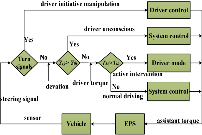
Driver state recognition
-
(2)
The execution layer mainly consists of the composite controller and control allocation module (see Figure 6). The composite controller consists of a H∞ controller based on the T-S model and a feedforward compensation controller. The H∞ controller is designed to obtain the expected assist torque based on the direction deviation and state information of the vehicle, obtained by the lane detection system and the vehicle sensors in real-time. The feedforward compensation controller is used to compensate for the additional torque and reduce the influence of external resistance on the desired target tracking. The control module mainly receives the vehicle’s dominant signal, which is transmitted by the driver’s state recognition system to send the driver torque signal and total assist torque signal to the motor controller.
Figure 6 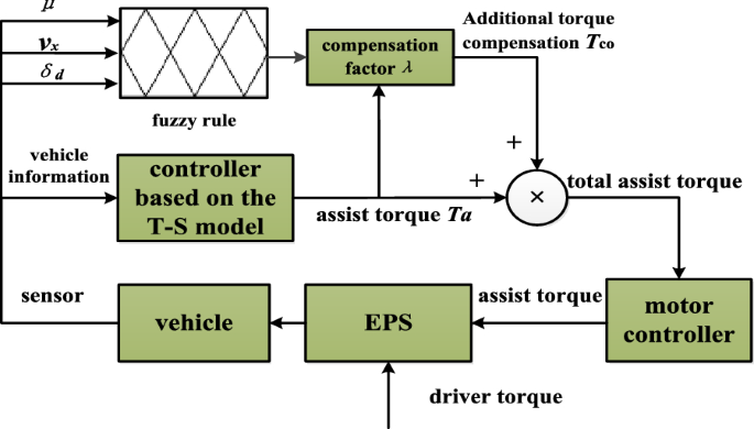
Feedforward compensation strategy
-
(3)
The execution layer is mainly composed of an EPS motor and its controller; it is used to receive all assist torque signals by the execution layer and subsequently operate the motor to realize active steering for deviation correction, ensuring that the vehicle is always near the centerline of the lane.


3.1 H∞ Controller Based on T-S Model
3.1.1 Driver-Vehicle-Road System Based on T-S Fuzzy Model
The nonlinear system can be described by the following T-S model:
then
where \(z\left( t \right) = \left( {z_{1} \left( t \right),\;z_{2} \left( t \right), \cdot \cdot \cdot ,\;z_{p} \left( t \right)} \right)\) are fuzzy variables of the driver-vehicle-road closed-loop system. The system fuzzy variable is \(v_{x} \left( t \right) = 55,\;70, \cdots ,\;115\;{\text{km/h}}\) and, in this paper, the fuzzy ruler is 5 and the fuzzy membership function is triangular. \(u_{d} \left( t \right)\) is the input to the system, \(x_{d} \left( t \right)\) is the state matrix of the system, and \(y_{d} \left( t \right) = R^{q \times l}\) is the output of the system. \(A_{di} \in R^{n \times n}\), \(B_{di} \in R^{n \times l}\), \(H_{di} \in R^{n \times l}\) and \(C_{di} \in R^{n \times q}\) are matrices corresponding to the section’s ith subsystem of the fuzzy system [20].
The state parameters of the driver-vehicle-road closed-loop system are the parameters in the vehicle-road system model, including the driver’s state parameters. The input of the system is \(u_{d} = T_{a} - T_{r}\), not including driver torque. The state equation of the system model can be expressed as:
where
Xv is the state parameter of the vehicle-road system, and Av and Bv are state matrices of the vehicle-road system. The fuzzy variables, state parameters, and input to the driver-vehicle-road closed-loop system are given and the T-S fuzzy model is as follows:
where \(\omega_{di} (z(t)) = \prod\limits_{j = 1}^{p} {M_{ij} (z(t))} = M_{ij} (v_{x} (t))\) is the validity degree of the ith rule and the value is the product of the membership functions associated with section i. Furthermore,
The T-S fuzzy model of the driver-vehicle-road closed-loop system is
3.1.2 Design of the H∞ Controller Based on the T-S Model
In this paper, the output of the controller based on the T-S fuzzy model is the desired assist torque for lane-keeping. Local state feedback controllers for 5 subsystems of the driver-vehicle-road T-S fuzzy model from Eqs. (12) and (13) are designed via parallel distributed compensation (PDC).
where \(K_{i}\) is the state feedback controller of the section of the ith local linear model. Considering the disturbance of the nonlinear system, the \(H_{\infty }\) control method should minimize the influence of disturbance on the system. Therefore, for a given scalar, the performance index should satisfy:
The smaller the norm of the performance index, the smaller the disturbance to the system.
The necessary conditions for the design of the traditional \(\text{H}_{\infty }\) state feedback controller is the existence of the positive definite matrix \(\varvec{X}\) and matrix \(\varvec{M}\), which satisfy the following formula [15]:
where Xv is the state parameters matrix of the reference vehicle-road system model, established in the second section of the present paper, and Av and Bv are the state matrixes of the reference vehicle-road system model. The feedback controller as the reference vehicle road system can be obtained using LMIs. Thus, the traditional \(\text{H}_{\infty }\) controller for the feedback matrix is as follows:
When designing the local state controller, the feedback gain \(K_{i}\) and minimum disturbance rejection \(\gamma\) can be obtained by using the LMI constraint and the linear objective function convex optimization problem, obtaining the optimal solution. The feedback gain and the minimum disturbance rejection are obtained. The necessary condition to satisfy the following formula is the existence of the positive definite matrix [21]:
where \({\varvec{Q}} = {\varvec{W}}^{\text{T}} {\varvec{W}},\)\({\varvec{W}} > {\mathbf{0}}\) indicates a positive definite matrix and \(M_{i}\) is the fuzzy membership function curve of fuzzy rule i. The controller parameters of each subsystem can be solved via the LMI toolbox in Matlab. The output of each local subsystem controller is:
The output of the controller based on the T-S fuzzy model is
The local controller feedback gain is established in the global performance index under the condition of control; when considering the global system control, to ensure the stability of each local subsystem under feedback when considering the global system control, gain subsystems \({\varvec{K}}_{i} = \left( {k_{1} ,k_{2} ,k_{3} ,k_{4} ,k_{5} ,k_{6} } \right)\) are considered such that global system stability can be guaranteed. The partial parameters of five local subsystem controllers are presented in Table 2.
3.2 Feedforward Compensation Controller
A large number of experiments show that the vehicle front-wheel cannot track the desired target in a lane-keeping active steering process. The external resistance during steering is not only related to the speed of the vehicle but also the road adhesion coefficient and the size of the front-wheel angle. A higher tire-road adhesion coefficient corresponds to a higher front-wheel angle, lower speed, and greater resistance on the front-wheel. Therefore, it is necessary to ensure tracking precision for lane-keeping to provide the corresponding additional assist torque, compensating for the effects of external resistance.
This paper aims to improve the lane-keeping performance by considering the road adhesion coefficient, the front-wheel angle, and the vehicle speed variation. The fuzzy rules are as follows. When the road adhesion coefficient and front-wheel angle are large, the additional compensation torque should be increased; when the speed is large, the external compensation torque should be reduced. For calculation convenience, the inputs to the fuzzy controller are the road adhesion coefficient \(\mu\), front-wheel angle \(\delta_{d}\), and vehicle speed \(v_{x}\), the output of the fuzzy controller is the compensating torque proportion \(\lambda \left( {T_{co} = \lambda T_{a} } \right)\). The domain variation range of \(\mu\) is \(U_{u} = \left[ {0.4,\;0.85} \right]\) and its fuzzy subset is \(\left\{\text{S, M, L} \right\}\), i.e., the small, medium, and large states of the road adhesion coefficient. The domain variation range of \(v_{x}\) is \(U_{vx} = \left[ {15,\;35} \right]\) and its fuzzy subset is \(\left\{ \text{S, M, L} \right\}\). The domain variation range of \(\delta_{d}\) is \(U_{\delta d} = \left[ {0,25} \right]\) and its fuzzy subset is \(\left\{ \text{S, M, L} \right\}\). The domain variation range of \(\lambda\) is \(U_{\lambda } = \left[ {0.1,\;0.5} \right]\) and its fuzzy subset is \(\left\{ \text{VS, S, M, L, VL} \right\}\), these are the smaller compensation, small compensation, medium compensation, high compensation and higher compensation [22], respectively. The input and output are all triangular membership functions and the fuzzy inference rules are presented in Table 3.
4 Simulation Experiment
The EPS model, driver model, and lane-keeping controller module were built in Matlab/Simulink. The Car-sim simulation vehicle was a C-class/sedan. The parameters for the EPS model and vehicle model are given in Table 4.
Straight road simulation conditions: The vehicle ran in a straight line at a fixed speed and the steering wheel angle was fixed at 10° due to the driver misoperation at 4.5 s, while the steering wheel torque did not exceed the threshold value.
The lane keeping assist system turned on when the lateral deviation reached a certain threshold and the EPS then received a lane-keeping assist torque signal sent by a controller; the control motor subsequently steered to correct deviation and direction. Vehicle lateral deviation and assist torques under speeds of 55 km/h, 70 km/h, and 85 km/h are compared, as shown in Figure 7.

Vehicle information on straight road at different speeds
Curve road simulation conditions: the vehicle trajectory is shown in Figure 8, the curvature radius of the first, second, and third curve is 155 m, 150 m, and 125 m, respectively.

Vehicle track
First simulation conditions (low road adhesion coefficient): the road adhesion coefficient was 0.5. The variation in speed was 55‒115 km/h, as shown in Figure 9. Figure 10 Compares the vehicle lateral position deviation, vehicle yaw angle, and yaw rate, under the control of the H∞ controller, the H∞ controller based on the T-S model, and the composite controller (feedforward control and H∞ control based on T-S).

Speed change curve

Vehicle driving situation on low road adhesion coefficient
Second simulation conditions (high road adhesion coefficient): the road adhesion coefficient was 0.85. Figure 11 Compares the vehicle lateral position deviation, vehicle yaw angle and yaw rate under the control of the H∞ controller, H∞ controller based on the T-S model, and the composite controller (feedforward control and H∞ control based on T-S).

Vehicle driving situation on high road adhesion coefficient
It is shown in Figure 7 that the driver state recognition system in the decision layer of the lane-keeping system can identify the status of the driver; when the driver does not operate the vehicle or mis-operates the vehicle, the system can switch vehicle control to ensure that the direction of the vehicle can be immediately corrected and the vehicle travels in the correct lane under the control of the assistance system, guaranteeing traffic safety.
-
(1)
It is shown in Figures 10, 11 that the H∞ control method based on the T-S driver-vehicle-road model can ensure that the vehicle travels in the centerline of the lane at different speeds, and both the lateral deviation and yaw angle are within the safe range. This control method can ensure the stale lane-keeping, and, among the three methods, the vehicle has better stability under composite control.
-
(2)
It is shown in Figures 10, 11 that the H∞ control method based on the T-S model can ensure that both the vehicle lateral deviation and yaw angle are within a safe range on roads with both a high and low adhesion coefficient. The vehicle driving deviation and performance index of the three methods, with a high adhesion coefficient, are compared and listed in Table 5. As Table 5 shows, compared with \(\text{H}_{\infty }\) control, the vehicle lateral deviation is reduced by 39.81% and the performance index is increased by 28.08% under the \(\text{H}_{\infty }\) control based T-S model. Vehicle lateral deviation is reduced by 51.52%, and the performance index is increased by 42.44% under composite control (\(\text{H}_{\infty }\) control based T-S model and feedforward control). The results show that the composite control method has smaller lateral deviation and a smaller performance index, reflecting the higher lane-keeping accuracy.
Table 5 Results of lateral deviation and performance index
5 Real Vehicle Experiment
To evaluate the reliability of the LKAS more accurately, a real vehicle test was conducted. The specific process is as follows.
-
(1)
When the vehicle is driving on the road, the vehicle camera mounted on the rearview mirror obtains a forward road image, which is sent to the digital signal processor (DSP) for lane detection and identification to determine lane information, i.e., lane shape, position, and vehicle information, direction, etc.
-
(2)
The vehicle position and direction deviation related to lane line are obtained through the transformation of the actual road environment and image coordinates.
-
(3)
DSP sends the information in the form of CAN to the CompactRIO device interface system.
-
(4)
Via speed, steering wheel angle, and torque sensors, the system obtains real-time vehicle speed, \(v_x\), steering wheel torque measurement, \(T_{se}\), and motor rotation signal, \(\theta_m\), and sends these signals to the CompactRIO interface system.
-
(5)
The CompactRIO interface system calculates the assist torque that the vehicle requires, according to the location information and the vehicle state information, which is received from the vehicle sensors.
-
(6)
The system sends the expected assist torque signal and the feedforward compensation control signal to the independently researched and developed motor angle controller. Then, the motor controller drive tracks the desired angle and performs active steering correction, finally achieving lane-keeping. The specific test flow is shown in the Figure 12.
Figure 12 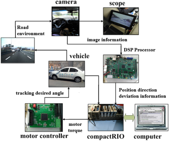
Structure of real vehicle experiment system

Experimental equipment included the experiment vehicle, steering wheel angle/torque sensor, gyroscope, VBOX (with GPS), CompactRIO, digital camera, image processor, motor controller and a CAN interface to connect the controllers, etc. The test equipment was installed in the experiment vehicle. Except for the accelerator pedal, controlled by the driver, the vehicle steering wheel was controlled by the controller and the system used a lane detection system installed in the vehicle to conduct automatic driving.
During the experiment, the road surface was processed and the high and low road adhesion coefficients were obtained. The speed ranged from 30 km/h to 65 km/h. The results are shown in Figure 13, comparing the lateral deviation under H∞ control based on the T-S model and composite control with feedforward compensation. The results of the real vehicle and simulation experiment with a high road adhesion coefficient are compared, as shown in Table 6. The experimental results show that the proposed control method ensures that the vehicle tracks the lane and achieves lane-keeping. Furthermore, they also show that the lane-keeping effect improves with a low adhesion coefficient condition, vehicle lateral deviation is smaller under composite control, and lane-keeping performance improves.

Vehicle driving situation for real vehicle experiment
6 Conclusions
-
(1)
The driver-vehicle-road closed-loop system based on the T-S model with the fuzzy variable of the longitudinal velocity is established. The lane-keeping controller was designed by the two-point preview driver model. The experiment results show that the designed controller can maintain the vehicle in proximity to the lane centerline and the system has good robustness and stability.
-
(2)
The driver state identification module can identify the driver status well and ensure that the LKAS can control the vehicle direction when the vehicle deviates from the correct route and the lateral deviation reaches a certain threshold in the driver unconscious or incorrect operation condition. Therefore, the vehicle is always traveling near the centerline, and traffic safety is guaranteed.
-
(3)
The \(\text{H}_{\infty }\) controller based on the T-S model is designed for the desired assist torque and considers external resistance affecting the wheel when steering. The feedforward compensation controller is designed to provide additional assist torque to compensate for external resistance. The simulation results show that the precision of lane-keeping is higher under composite control.
-
(4)
The lane recognition system, based on machine vision, and lane-keeping control system are installed on the real vehicle. The image processor, decision controller, and motor controller communicate via CAN. Multiple real vehicle tests were conducted to demonstrate that the vehicle experiment platform was built to achieve the lane-keeping function and to guarantee the stability of the vehicle during the process.
References
A Cartwright . The Psychological Effects of Road Traffic Accidents (RTAs): An Exploration of a United Kingdom Medico-Legal Examiner’s Career of RTA Assessments. Psychiatry Psychology & Law, 2017, 25(2): 1-22.
N Zhao, J B Yuan, X U Han. Survey on intelligent transportation system. Computer Science, 2015, 28(1): 1-5.
S A Ridella, A Lie. The international technical conference on the enhanced safety of vehicles (ESV). Traffic Injury Prevention, 2012, 14 Suppl(3): 167.
C Hu, Y Qin, H Cao, et al. Lane-keeping of autonomous vehicles based on differential steering with adaptive multivariable super-twisting control. Mechanical Systems and Signal Processing, 2019, 125(JUN.15): 330-346.
K Chen, X Pei, D Sun, et al. Active steering control for autonomous vehicles based on a driver-in-the-loop platform: A case study of collision avoidance. Proceedings of the Institution of Mechanical Engineers Part I Journal of Systems and Control Engineering, 2019, 233(1): 095965181984700.
K Osman, J Ghommam, H Mehrjerdi, et al. Vision-based curved lane-keeping control for intelligent vehicle highway system. Proceedings of the Institution of Mechanical Engineers, 2019, 233(8): 961-979.
A Merah, K Hartani, A Draou. A new shared control for lane-keeping and road departure prevention. Vehicle System Dynamics, 2016, 54(1): 1-16.
W Kim, Y S Son, C C Chung. Torque overlay-based robust steering wheel angle control of electrical power steering for a lane-keeping system of automated vehicles. IEEE Transactions on Vehicular Technology, 2015, 65(6): 1-1.
J H Yang, W Y Choi, S H Lee, et al. Autonomous lane-keeping control system based on road lane model using deep convolutional neural networks. 2019 IEEE Intelligent Transportation Systems Conference – ITSC, IEEE, 2019.
K L R Talvala, K Kritayakirana, J C Gerdes. Pushing the limits: From lanekeeping to autonomous racing. Annual Reviews in Control, 2011, 35(1): 137-148.
Y S Son, W Kim, S Lee, et al. Robust multirate control scheme with predictive virtual lanes for lane-keeping system of autonomous highway driving. IEEE Transactions on Vehicular Technology, 2015, 64(8): 3378-3391.
D Tan, W Chen, J Wang, et al. Human-machine sharing and hierarchical control based lane departure assistance system. Journal of Mechanical Engineering, 2015, 51(22): 98. (in Chinese)
D Tan, W Chen, H Wang, et al. Shared control for lane departure prevention based on the safe envelope of steering wheel angle. Control Engineering Practice, 2017, 64(Jul.): 15-26.
U Rosolia, S D Bruyne, A G Alleyne. Autonomous vehicle control: A nonconvex approach for obstacle avoidance. Control Systems Technology, IEEE Transactions on, 2017, 25(2): 469-484.
Krispin A Davies, Alejandro Ramirez-Serrano. Performance analysis of a nonlinear model predictive control for safe, robust and semi-autonomous aerial vehicle flight in confined spaces. International Conference on Robotics & Automation, 2015.
D Jayaprasanth, S Kanthalakshmi. Improved state estimation for stochastic nonlinear chemical reactor using particle filter based on unscented transformation. Control Engineering and Applied Informatics, 2016, 18(4): 36-44.
L H Luo. Steering control for lane keeping system based on MPC. Journal of Shanghai Jiaotong University, 2014, 48(7):1015-1020.
J B Cicchino, D S Zuby. Prevalence of driver physical factors leading to unintentional lane departure crashes. Traffic Injury Prevention, 2017, 18(5): 481-487.
J Lee, J Choi, K Yi, et al. Lane-keeping assistance control algorithm using differential braking to prevent unintended lane departures. Control Engineering Practice, 2014, 23(1): 1-13.
J B Cicchino, A T Mccartt. Experiences of model year 2011 Dodge and Jeep owners with collision avoidance and related technologies. Journal of Crash Prevention & Injury Control, 2015, 16(3): 298-303.
S J Anderson, S C Peters, T E Pilutti, et al. Design and development of an optimal-control-based framework for trajectory planning, threat assessment, and semi-autonomous control of passenger vehicles in Hazard Avoidance Scenarios. International Journal of Vehicle Autonomous Systems, 2011, 8(2):190-216.
Y Wu, Z Huang, L Liu. Differential braking control for lane departure avoidance. China Mechanical Engineering, 2013, 24(21): 2977-2981.
C Chen, Y Jia, J Du, et al. Lane-keeping control for autonomous 4WS4WD vehicles subject to wheel slip constraint. American Control Conference, IEEE, 2012.
A T Nguyen, C Sentouh, J C Popieul. Driver-automation cooperative approach for shared steering control under multiple system constraints: Design and experiments. Industrial Electronics, IEEE Transactions on, 2017, 64(5): 3819-3830.
N M Enache, S Mammar, M Netto, et al. Driver steering assistance for lane-departure avoidance based on hybrid automata and composite Lyapunov function. IEEE Transactions on Intelligent Transportation Systems, 2010, 11(1): 28-39.
H Wang, Q Wang, W Chen, et al. Multi-mode human–machine cooperative control for lane departure prevention based on steering assistance and differential braking. IET Intelligent Transport Systems, 2020, 14(6): 578-588.
L Menhour, A Charara, D Lechner. Switched LQR/ H∞ steering vehicle control to detect critical driving situations. Control Engineering Practice, 2014, 24(24): 1-14.
X Wang, Q Wang, J Wang. Human-machine cooperative steering PDC/H∞ control strategy based on driver model with near and far visual angels. Journal of Mechanical Engineering, 2015, 51(22): 98.
D I Katzourakis, N Lazic, C Olsson, et al. Driver steering override for lane-keeping aid using computer-aided engineering. IEEE/ASME Transactions on Mechatronics, 2015, 20(4): 1-10.
A Marouf, M Djemai, C Sentouh, et al. A new control strategy of an electric-power-assisted steering system. IEEE Transactions on Vehicular Technology, 2012, 61(8): 3574-3589.
I Gamal, A Badawy, A M W Al-Habal, et al. A robust, real-time and calibration-free lane departure warning system. IEEE International Symposium on Circuits & Systems, IEEE, 2019.
Acknowledgements
The authors would like to thank Dr. Dongkui Tan and Dr. Zhenya Wei for their guidance and assistance in the vehicle tests.
Funding
Supported by National Natural Science Foundation of China (Grant Nos. 51675151, U1564201) and Open Fund of the Key Laboratory of Advanced Perception and Intelligent Control of High-end Equipment of Ministry of Education (Grant No. GDSC202013).
Author information
Authors and Affiliations
Contributions
WC was in charge of the whole trial; WC also wrote the whole manuscript; LZ assisted with sampling and laboratory analyses. All authors read and approved the final manuscript.
Authors’ Information
Wuwei Chen received his Ph.D. degree from Anhui Institute of Optics and Fine Mechanics, Chinese Academy of Sciences, China, in 1999. He is currently a Professor at School of Automotive and Transportation Engineering, Hefei University of Technology, China. He is the author or co-author of more than 260 research publications. He has engaged in more than ten sponsored projects. His current research interests include vehicle dynamics and integrated control, driving-assistance systems, as well as intelligent vehicles.
Linfeng Zhao received his Ph.D. degree from Hefei University of Technology, China, in 2010. He is currently an Associate Professor at School of Automotive and Transportation Engineering, Hefei University of Technology, China. His current research interests include vehicle dynamics and control, electric power steering system, and intelligent vehicles.
Huiran Wang received his M.S. degree from Hefei University of Technology, China, in 2016. He is currently working toward the Ph.D. degree in automotive engineering at Hefei University of Technology, China. His research interests include intelligent vehicle dynamics and control and human-machine sharing control.
Yangcheng Huang received his master degree from Hefei University of Technology, China, in 2017. His research interest is vehicle dynamics and control. He is currently a strategy engineer at HeFei Softec Auto-Electronic Co., Ltd.
Corresponding author
Ethics declarations
Competing Interests
The authors declare that they have no competing interests.
Rights and permissions
Open Access This article is licensed under a Creative Commons Attribution 4.0 International License, which permits use, sharing, adaptation, distribution and reproduction in any medium or format, as long as you give appropriate credit to the original author(s) and the source, provide a link to the Creative Commons licence, and indicate if changes were made. The images or other third party material in this article are included in the article's Creative Commons licence, unless indicated otherwise in a credit line to the material. If material is not included in the article's Creative Commons licence and your intended use is not permitted by statutory regulation or exceeds the permitted use, you will need to obtain permission directly from the copyright holder. To view a copy of this licence, visit http://creativecommons.org/licenses/by/4.0/.
About this article

Cite this article
Chen, W., Zhao, L., Wang, H. et al. Parallel Distributed Compensation /H∞ Control of Lane-keeping System Based on the Takagi-Sugeno Fuzzy Model. Chin. J. Mech. Eng. 33, 61 (2020). https://doi.org/10.1186/s10033-020-00477-9
Received:
Revised:
Accepted:
Published:
DOI: https://doi.org/10.1186/s10033-020-00477-9