- Original Article
- Open access
- Published:
Automatic Scallion Seedling Feeding Mechanism with an Asymmetrical High-order Transmission Gear Train
Chinese Journal of Mechanical Engineering volume 33, Article number: 10 (2020)
Abstract
The current automatic scallion-transplanting machine is a complicated mechanism composed of two linkage mechanisms and two band carriers. It delivers seedlings inefficiently because of the movement limitations of the linkage mechanism. This paper proposes a new high-order non-circular gear train for an automatic scallion-seedling feeding mechanism. The proposed gear train has an asymmetrical transmission ratio; i.e., its transmission ratio varies. This allows the mechanism’s execution component to move in a long displacement and rotate in a large rotation angle. The long displacement enables the execution component to reach the designed working position, and the large rotation angle allows it to feed a scallion in the required pose. A mathematical model for calculating the asymmetrical transmission ratio was established according to the closure requirements and the full-cycle motion of the driven gear pitch curve. Then, the parameter-design model of the new seedling-feeding mechanism was established, based on precise pose points and trajectory-shape control points. Moreover, an aided-design program was developed to obtain the parameter-solution domain of the scallion-seedling feeding mechanism. The mechanism parameters, which met the seedling-feeding function, were optimized to determine the transmission ratio, using a program and a kinematic simulation. Finally, a prototype of the mechanism was produced, and a seedling-feeding experiment was carried out. One-thousand seedlings were tested at a rate of 100 seedlings per minute, and the statistical success rate was 93.4%. Thus, the automatic scallion-seedling feeding mechanism significantly improves the efficiency of automatically transplanting scallions.
1 Introduction
The scallion is an important vegetable with a high economic value. Scallion cultivation has a long history in China. The average annual planting area is about 500000 hm2 at present, so an automated system is necessary. When transplanting scallions, the distance between seedlings is always less than 10 cm. A soft disc-type transplanter can better meet the requirements of short-distance planting [1].
At present, the seedlings are delivered to the disc-type transplanter by a combination of two linkage mechanisms and two band carriers. The structure is complicated and the transplanting is slow because of the disadvantages of the linkage mechanism [2]. With the growing demand for mechanized agriculture, a new scallion-delivery mechanism is urgently needed.
In transplanting-machinery research, Xin et al. [3, 4] researched a double-crank potted rice-seedling transplanting mechanism; an “8”-shaped trajectory was achieved by optimizing the parameters. Jin et al. [5] combined this mechanism with a programmable logic controller to investigate an intelligent transplanting mechanism.
Japanese and Korean scholars proposed a slide-type transplanting mechanism [6] and a double slide-type transplanting mechanism [7], respectively. The parameters of the slide-transplanting mechanism were optimized by Li et al. [8] and Ji et al. [9], thereby improving the mechanism’s transplanting performance. Because of structural limitations, these mechanisms adopt a single-type transplanting arm, so improving the efficiency is difficult.
A non-circular planetary gear-train mechanism can achieve special kinematic regularities, which are widely applied in rice- and vegetable-transplanting machines because of the unequal speed transmission [10]. Zhou et al. [11] designed a transplanting mechanism with planetary Bézier gears. Li et al. [12] researched a non-circular–gear computation method, based on the seedling needle-tip point’s static trajectory in the transplanting mechanism.
Zhao et al. [13] proposed a reverse design of the D-shaped trajectory for clamping the rice seedlings. To create a special transplanting trajectory with a sharp tip, Zhao et al. designed a seedling-picking mechanism with two unequal-amplitude characteristics [14]. Yu et al. [15, 16] proposed a transplanting mechanism with intermittent non-circular gears, based on an intermittent unequal-speed transmission. Ye et al. [17, 18] studied the kinematics and dynamics of the transmission and applied the mechanism to transplanting rice and vegetable seedlings. Sun et al. [19] synthesized the gear-train mechanism configuration and investigated a variety of available mechanisms.
A planetary gear-train mechanism has the relative advantages of a simple structure, double transplanting arms that can be arranged conveniently, and high efficiency. In this paper, a new automatic scallion-seedling feeding mechanism is proposed, based on an original non-circular planetary gear-train mechanism, to realize the special requirements of automatic scallion-seedling feeding.
Nowadays, most non-circular planetary gear-train mechanisms have single-order non-circular gear trains; i.e., while the planetary carrier rotates one round, the execution component rotates one round, relative to the planetary carrier. When the execution component is collinear with the planetary carrier, its terminal point will be located at the farthest or nearest location that the mechanism can reach; this happens twice in one movement cycle [20]. Taking the rotation axis of the planetary carrier as the center, an annulus field can be defined by the farthest and nearest locations. The annulus is the mechanism’s trajectory space.
A common design goal of single-order non-circular planetary gear-train transplanting mechanisms is to vertically push or plant a seedling. Thus, the rotation angle of the execution component should be 55°–60°. However, for automatic scallion transplanting, the seedlings should be fed horizontally into the soft disc-type transplanter. This means the rotation angle of the execution component is at least 145°. Moreover, the displacement from the seedling-clamping position to the seedling-dropping position is larger. A single-order planetary gear train cannot achieve this requirement.
Junhua Tong designed an automatic box-picking mechanism with an elliptic-circular–gear high-order planetary gear train; except for the three-order solar gear, all of the other gears in the mechanism are single-order gears. The inner cycloid trajectory is formed by the movement of the terminal point of the execution component. During a motion cycle, the terminal point reaches the farthest and nearest locations three times each [21]. The rotation angle of the execution component can change in the range of 0°–720°.
The maximum displacement of the terminal point of the execution component in space is also greatly increased, compared with a single-order planetary gear train of the same mechanism size. The number of extreme locations in the trajectory is related to the order of the solar gear in the planetary gear-train mechanism.
The execution component of a high-order planetary gear train rotates in more than one circle, relative to the planetary carrier in one motion cycle. When the execution component rotates in one circle, relative to the planetary carrier, its terminal point passes once through both the farthest and nearest locations. A high-order non-circular planetary gear-train mechanism can reach the farthest and nearest location many times. This characteristic enables the execution component to realize a long displacement and a large rotation angle.
In existing research on high-order non-circular gear transmissions, Lin et al. [22] designed a high-order elliptical bevel-gear pair and a high-order elliptical modified bevel-gear pair [23]. Xu et al. [24] designed a high-order Fourier non-circular gear. These transmission ratios are completely symmetrical, which means that only one section of the transmission ratio can be designed. The corresponding symmetrical section must match, and, therefore, cannot be changed independently. Moreover, the motion regularity of the execution component is also strictly symmetric, which means it is difficult to flexibly design the kinematic regularities.
This study proposed an asymmetrical high-order transmission and a design method for the asymmetrical transmission ratio of a high-order non-circular gear train. Firstly, the gear-train structure was designed. Secondly, the scallion-seedling feeding mechanism of the planetary gear train with an asymmetrical high-order non-circular gear was optimized to realize the large rotation and long displacement of the execution component. Finally, the design correctness was verified through motion simulations and a prototype experiment.
2 Design of the Asymmetrical High-Order Non-circular Gear Train
2.1 Structure and Working Principle
The structural model of the asymmetrical two-order non-circular gear train is shown in Figure 1. Taking this model as an example, the asymmetrical high-order non-circular gear train is illustrated.

Schematic diagram of the asymmetrical-transmission high-order non-circular gear train. 1. The first driving gear; 2. The second driving gear; 3. The first driven gear; 4. The second driven gear
Figure 2 shows that both the first driving gear (1) and the second driving gear (2) are incomplete non-circular gear pieces that form a combined driving gear. The sum of the center angle of the pitch curve, corresponding to the driving gear profile of the two active wheels (i.e., the sum of Ψ1 and Ψ2 in Figure 2), is 360°. The first driven gear (3) and the second driven gear (4) are both non-circular gears that are fixed onto the same shaft. The first driving gear (1) and the first driven gear (3) are a conjugated transmission, and the second driving gear (2) and the second driven gear (4) are a conjugated transmission.

Central angle of the two driving gears
The working principle of the asymmetrical high-order non-circular gear train is as follows. In a movement cycle, when the driving gear rotates in a clockwise direction, the first driving gear and the first driven gear engage to work, as shown in Figure 3a. While the first driven gear rotates around, all of the teeth of the first driving gear participate in the movement transmission; the total rotational angle is Ψ1, as shown in Figure 3b. Meanwhile, the second driving gear (2) and the second driven gear (4) engage to work, as shown in Figure 3c. While the second driven gear rotates 360°, all of the teeth of the second driving gear rotate Ψ2, as shown in Figure 3d.

Four critical positions in a movement cycle
During one rotation cycle of the driving gears, the driven gears rotate two rounds, which means the gear train has the transmission characteristic of a high-order gear train. On the other hand, both the driving gear and the driven gear are non-circular gears with an asymmetrical pitch curve. Thus, the gear train also has the asymmetrical transmission characteristic of a non-circular gear train.
The change of the gear-train structure is also regular when the gear-train order changes. For example, in an asymmetrical-transmission n-order non-circular gear train, the driving gears are composed of n incomplete non-circular gears, and the number of driven gears is consistent with the driving gears.
2.2 Design of the Asymmetrical-Transmission High-order Non-circular Gear Train
Figure 4 illustrates the rotation-angle curves of the different gear trains. The thick line is the transmission ratio of the asymmetrical second-order gear train. The thin line is the transmission ratio of the symmetrical second-order gear train, which consists of a second-order non-circular driving gear and a single-order non-circular driven gear. Regardless of the type of gear train, when the driving gears rotate 360°, the driven gears rotate 720°, which means they all have high-order transmission characteristics.

Rotation-angle curves of the symmetrical and asymmetrical second-order non-circular gear trains
The angle curve of the symmetrical transmission second-order gear train undergoes two identical periodic changes in one motion cycle; the same characteristic appears on the transmission-ratio curve in Figure 5. The thin line is the transmission-ratio curve of the symmetrical-transmission second-order gear train; it also undergoes two identical periodic changes in one transmission cycle. If the Cartesian coordinate system was transformed into a polar coordinate system, the symmetry of the transmission ratio would be more obvious.

Transmission ratio of the symmetrical and asymmetrical second-order non-circular gear trains
The gear-pitch curve of the gear train can be calculated according to Eqs. (1)–(3), where a is the center distance between the two gears. The gear-pitch curves are shown in Figure 6.

Pitch curve of the symmetrical-transmission second-order non-circular gear train
Neither the rotation-angle curve nor the transmission-ratio curve (the thick line shown in Figure 5) of the asymmetrical transmission second-order gear train shows the symmetry characteristic. Moreover, it is not possible to directly calculate the gear-pitch curves by using the equations mentioned above. To obtain the gear-pitch curve, the transmission-ratio curve of the asymmetrical-transmission second-order non-circular gear train must be processed as follows:
- 1)
Two points, P1 and P2, should be selected on the transmission-ratio curve to divide the curve into three parts, as shown by the thin line in Figure 7. The ordinates of the two points are equal, which means the values of the transmission ratio i of the two points are equal. To ensure the closure of the driven gear’s pitch curve, the abscissas of the two points should satisfy Eq. (4):
Figure 7 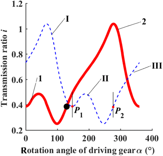
Divided and combined gear-ratio curves. I, II, III. Curve section of original transmission ratio; 1, 2. Curve section of new transmission ratio
$$\Delta \beta = \int_{{\alpha_{1} }}^{{\alpha_{2} }} {\frac{1}{i}\,} {\text{d}}\alpha = 360^\circ ,$$(4)where α1 is the abscissa of point P1 and α2 is the abscissa of point P2. The transmission-ratio curve between the two points can be used to calculate one pair of gear-pitch curves, and the pitch curve of the driven gear must be closed. The rest of the transmission-ratio curve, outside the two division points, must satisfy Eq. (5). Thus, the second pair of gear-pitch curves can be calculated:
$$\Delta \beta_{1} + \Delta \beta_{2} = \int_{0}^{{\alpha_{1} }} {\frac{1}{i}\,} {\text{d}}\alpha + \int_{{\alpha_{2} }}^{360} {\frac{1}{i}} \,{\text{d}}\alpha = 720^\circ - \int_{{\alpha_{1} }}^{{\alpha_{2} }} {\frac{1}{i}} \,{\text{d}}\alpha = 360^\circ .$$(5) - 2)
In Figure 7, points P1 and P2 divide the original transmission-ratio curve into three parts; Part 1 is moved to the end to form a new transmission ratio, shown by the thick line in the same figure. Part I of the new transmission-ratio curve is Part 2 of the original transmission-ratio curve. Part II is formed by the combination of Part 1 and Part 2.

The gear-pitch curves can be designed separately using the two parts of the new transmission-ratio curve, according to Eqs. (1)–(3). As shown in Figure 8, the thick lines are the pitch curve of the first driving gear and the first driven gear; the thin lines are the pitch curves of the second driving gear and the second driven gear, as shown in the thick line segment of Figure 7. The second part corresponds to the second pair of main driven-wheel gear-pitch curve groups, shown in the thin line segment in Figure 7.

Pitch curves of the two pairs of main driven gears. 1. Pitch curve of the first driving gear; 2. Pitch curve of the second driving gear; 3. Pitch curve of the first driven gear; 4. Pitch curve of the second driven gear
The design of the high-order gear train obeys the same rule: The asymmetrical-transmission high-order gear train consists of n pairs of driving and driven gears; thus, n points must be found, using the same principle to divide the transmission-ratio curve. After that, the transmission-ratio curve should be recombined to design the gear-pitch curves.
3 Kinematic Analysis of the Scallion-Seedling Feeding Mechanism
The automatic scallion-seedling feeding mechanism cooperates with the soft disc-type transplanter. The working process follows: The seedling-clamping manipulator of the automatic scallion-seedling feeding mechanism removes the scallion seedlings from the seedling tray and transports them to the flexible disc planter; then, the flexible disc planter plants them into the soil.
As shown in Figure 9, the angle between the seedling box and the horizontal plane is 60°, so at the seedling-feeding position, the rotation angle of the execution component (seedling-clamping component) should be 150°. At the seedling-feeding position, the scallion seedlings are horizontally fed into the soft disc-type transplanter. The work trajectory was designed to look like the Arabic number “8” as shown in Figure 9.

Trajectory design of scallion-seedling feeding
The asymmetrical-transmission second-order non-circular gear train was used to design the scallion-seedling feeding mechanism. The terminal point of the seedling clamp reaches the farthest location twice; these can be designed as the seedling-clamping position and the seedling-feeding position. Because of the characteristics of the asymmetric transmission, the design flexibility of the seedling-clamping component will be greater, to meet the long displacement and large rotation-angle requirements of the scallion-seedling feeding function.
4 Optimal Parameter Design for the Scallion-Seedling Feeding Mechanism
The special 8-shaped trajectory required by the scallion-seedling feeding mechanism should meet the requirements of the displacement and the precise posture at some critical position. The asymmetric transmission ratio is critical for the mechanism parameter design. The optimal design of the scallion-seedling feeding mechanism is realized using a method based on precise poses and trajectory control.
4.1 Mechanism Parameter-Solving Model
The precise pose point is defined by a pair of rectangular coordinates and an angle, which shall be the critical position on the trajectory; e.g., the seedling-clamping position or the seedling-feeding position. The parameter-solving model is established in two steps:
Step 1: The planetary gear-train scallion-seedling feeding mechanism is considered as a combination of the bar-group and the gear train. The rigid-link guidance theory is used to calculate the mechanism parameter, so as to obtain the transmission ratio of the planetary gear train [25, 26]. Firstly, three precise positions Pi (xi, yi) and postures θi (i = 1, 2, 3) are given. As shown in Figure 10, the mechanism was simplified into a bar-group model and its motion was analyzed.

Motion analysis of the bar-group model. 1. Planetary carrier; 2. Seedling-clamping manipulator
Eq. (6) describes the three precise pose conditions Pi (xi, yi) and θi. Among the equations, \(\theta_{1i} = \theta_{i} - \theta_{1}\) is the rotation angle of the seedling-clamping manipulator when its end point moves from P1 to Pi. Eq. (6) is used to calculate Eq. (7) and obtain Eq. (8):
In Eq. (8), x0 and y0 are the coordinate values of the fixed hinge point A0. Eq. (8) is used to calculate Eq. (9), where r is the length of the planetary carrier. Then, the solution curve of the fixed hinge point A0 can be calculated. The solution curve of the moving hinge point Ac1 (xc1, yc1) can be calculated using Eq. (10):
The parameter-solution domain of the scallion-seedling feeding mechanism can be obtained by Eq. (11). l is the length of the seedling-clamping manipulator, φ21 is the initial angle between the manipulator and the horizontal plane, and φ11 is the initial angle between the planetary carrier and the horizontal plane.
Step 2: A few precise pose points cannot guarantee that the generated trajectory shape will meet the expectations. Hence, it is necessary to add some trajectory-shape control points to control the shape of the trajectory. As shown in Figure 11, Pi are the precise pose points, and Ei are the trajectory-shape control points.

Expected trajectory formed by the pose points and control points
Angles Ф1i and Ф2i of the planetary carrier and the seedling-clamping manipulator, relative to the initial position at each pose point and control point, can be obtained according to Eq. (12). The relative rotation curve can be obtained by a B-spline curve-fitting technique [27]. After fitting the relation-angle curve between the planetary carrier and the seedling-clamping component, the transmission ratio of the planetary gear train can be calculated from Eq. (13). When the planetary carrier and the seedling-clamping component rotate in the same direction, the sign is negative, and vice versa. The actual generated trajectory can be calculated by Eq. (14):
Compared with the optimal forward and reverse designs of the existing gear-train transplanting mechanism, this method has the advantages of greatly reducing the number of initially required parameters, ensuring the precise pose of the mechanism at important working positions, and obtaining more than one set of mechanism parameters that meets the requirements of the work function. If the bar-group parameter is not satisfactory, a second design can be quickly carried out by changing the trajectory-shape control points.
5 Optimized Design of the Mechanism Parameters
The working requirements of the scallion-seedling feeding mechanism were analyzed, and the three precise pose points were determined as shown in Table 1, where P1 and P3 are the seedling-clamping position and seedling-feeding position, respectively. P2 is the point at the end of the seedling-clamping manipulator, which needs to move 30 to 40 mm in a nearly straight line after clamping the seedlings, to ensure that the seedlings are pulled vertically from the tray to avoid damaging their roots. The parameter-solution domain of the mechanism is calculated using the above method, and the solution curves of the two hinge points are shown in Figure 12.

Solution curves of the two hinge points
The trajectory must satisfy the working requirements. The seedling-clamping position and the seedling-feeding position are the critical working positions of the mechanism. The seedling-clamping component clamps the stem of the scallion seedling at point P1, removes it from the seedling box, and then feeds it at point P3. According to the above situation, two optimization objectives are set:
- 1)
Point P1 should be at the rightmost end of the entire trajectory, or at least within an acceptable distance from there. Considering the size of the seedling box, and to prevent the transplanting claw from entering the box too deeply, the distance from point P1 to the rightmost point is set not to exceed 5 mm;
- 2)
P3 should be kept at the lowest position of the entire trajectory, or at least within an acceptable distance from there. Because the transplanting claw must be some distance from the soft disc-type transplanter when releasing the seedling, the distance is set not to exceed 10 mm.
As shown in Figure 13, both trajectories pass through the pose points. The expected trajectory and the mechanism parameters must be designed and optimized in combination with the seedling-feeding operation requirements. Table 2 shows the coordinates of trajectories 1 and 2, which are shown in Figure 12 at critical positions. Trajectory 1 is obviously better than trajectory 2.

Track comparison of the two sets of parametric solutions
The optimal mechanism parameters obtained using the above optimization principle are shown in Table 3. To improve the design efficiency, based on the above mathematical model, the mechanism optimization design software was compiled using the GUI module of MATLAB, as shown in Figure 14.

Mechanism-optimization design software
With the optimal parameters of the scallion-seedling feeding mechanism, the relative rotation curve of the planetary carrier and the seedling-clamping component can be calculated, and then the transmission-ratio curve can be calculated. All values are shown in Figure 15.

Relative rotation-angle curve and transmission-ratio curve
The planetary gear train is divided into two pairs of gear trains. The first stage adopts an asymmetrical high-order non-circular gear pair and the second stage adopts a pair of circular gear pairs with the same parameters. It can be seen from Eq. (15) that all features of the total gear ratio of the gear train are completely retained in the first stage of the asymmetrical high-order non-circular gear pair.
6 Kinematic Simulation and Verification of the Mechanism
The structure of the scallion-seedling feeding mechanism was designed according to the optimal parameters, and the mechanism was modeled and virtually assembled using the Solidworks solid-modeling software. As shown in Figure 16a, the planetary gear train of the scallion-seedling feeding mechanism consists of two pairs of gear trains. One is the asymmetrical-transmission second-order non-circular gear train; the other is a pair of circular gears with the same parameters.

Gear-train model and simulated mechanism track
The three-dimensional model was imported into the ADAMS dynamics simulation software to obtain the trajectory of the end point of the seedling-clamping manipulator. The simulation result is shown in Figure 16b. The trajectory obtained from the virtual simulation was compared with the one obtained from the theoretical calculation, as shown in Figure 16c. Referring to the data of critical working points P1 and P3, as shown in Table 4, it can be seen that the error value between the two at the key working points is very small. The theoretical trajectory is basically consistent with the simulated trajectory, which verifies the correctness of the structural design.
7 Experiment and Result Analysis
The purposes of the experiment are as follows:
- 1)
Observe whether the mechanism’s posture at each precise pose point is consistent with the theoretical design value;
- 2)
Observe whether the working trajectory formed by the mechanism conforms to the theoretical design; and
- 3)
Observe whether the mechanism can realize the complete green-onion–seedling feeding operation.
Three-week-old onion seedlings were selected for the test subjects; they are shown in Figure 17. An experimental platform used for feeding scallion seedlings was set up in the Transplanting Equipment Technology Laboratory, as shown in Figure 18. The experimental platform consisted of the rack, motor, seedling box, and scallion-seedling feeding mechanism.

Scallion seedlings

Experimental platform
During the experiment, the trajectory and the poses, when the mechanism passed the given three pose points, were analyzed using high-speed–photography analysis software, as shown in Figure 19.

Trajectory and posture verification
The actual trajectory (Figure 19a) was equal to the theoretical movement trajectory in Figure 16c. A comparison of the trajectories showed that the mechanism could satisfy the trajectory and poses required for the scallion-seedling feeding work. After 35 experiments, the feeding-mechanism angles at the three precise positions were measured and their average values were obtained.
When comparing the theoretical angle values of the three precise pose points with the average of the actual measured results, as shown in Table 5, the angle errors were all less than 3°, which means the experimental results were within the allowed error range of the mechanism experiment. The causes of the errors were as follows:
- 1)
Error machining the mechanism parts;
- 2)
Mechanism-installation error;
- 3)
Experimental-equipment error.
The results of the scallion-seedling feeding experiment are shown in Figure 20. The mechanism can well complete the scallion-seedling feeding work.

Experimental results
In the experiment, the set feeding-success criterion was for the seedlings to be taken out of the seedling box and fed smoothly. A total of 1000 seedlings were tested at a rate of 100 seedlings per minute, and the statistical success rate was 93.4%. The results of the seedling-feeding experiment shows that the mechanism has high performance.
8 Conclusions
An automatic scallion-seedling feeding mechanism with an asymmetrical-transmission high-order non-circular planetary gear train was proposed in this paper to improve the efficiency of automatic scallion transplanting. The conclusions of this study are summarized as follows.
- (1)
After analyzing the working trajectory and transmission characteristics of single-order and high-order planetary gear-train mechanisms, an asymmetrical high-order non-circular gear train structure was proposed. This mechanism was compact and flexible in the kinematic design, and could efficiently feed seedlings.
- (2)
To meet the scallion-seedling feeding function, a parameter-solution model of the asymmetrical- transmission second-order non-circular–gear planetary gear-train mechanism was established. Using a method based on the precise pose points and trajectory-shape control points, optimal mechanism parameters and an asymmetrical transmission ratio that met the seedling-feeding function were obtained. Kinematic simulations of the mechanism verified the validity and correctness of the design method, which represents a different strategy for an automatic scallion-seedling feeding mechanism.
- (3)
During the high-speed–photography and seedling-feeding experiments, the angles of the seedling-clamping manipulator were measured when the mechanism passed each critical working position; the values were 167.41°, 157.43°, and 17.26°. The measured values differed from the theoretical values by 2.41°, 2.43°, and 2.26°, respectively. The efficiency of the proposed mechanism was verified within the allowable error range. This research provided a simple and efficient scheme for an onion-seedling feeding device.
References
S Wang, C H Li, W Gao. Simulation and parametric analysis of vegetable seedling transplanting mechanism. Applied Mechanics and Materials, 2011(2): 4690-4694. (in Chinese)
X Jin, X W Du, G S Gen, et al. Experiment on planting system of 2ZDJ-2 transplanter. Transactions of the Chinese Society for Agricultural Machinery, 2015, 46(12): 26-31. (in Chinese)
L Xin, Z J LV, W Q Wang, et al. Optimal design and development of a double-crank potted rice seedling transplanting mechanism. Transactions of the ASABE, 2017, 60(1): 31-40.
Y Zhao, H X Zhu, L Xin, et al. Mechanism analysis and experiment of transplanting mechanism with fitting gear five-bar for rice pot seedling. Transactions of the Chinese Society for Agricultural Engineering, 2016(1): 12-21. (in Chinese)
X Jin, K X Zhao, J T Ji, et al. Design and implementation of intelligent transplanting system based on photoelectric sensor and PLC. Future Generation Computer Systems, 2018, 88: 127-139.
Azhar lqbal Muftik, Abdul Shakoor Khan. Performance evaluation of yanmar paddy transplanter in Pakistan. AMA, 1995, 26(1): 31-36, 40.
W C Choi, D C Kim, I H Ryu, et al. Development of a seedling pick-up device for vegetable transplanters. Transactions of the ASAE, 2002, 45(l) : 13-19.
H Li, W B Cao, S F Li, et al. Development of 2ZXM-2 automatic plastic film mulching plug seedling transplanter for vegetable. Transactions of the Chinese Society of Agricultural Engineering, 2017, 33(15): 23-33. (in Chinese)
J T Ji, L H Yang, X Jin, et al. Design and parameter optimization of planetary gear-train slip type pot seedling planting mechanism. Transactions of the Chinese Society of Agricultural Engineering, 2018, 34(18): 83-92. (in Chinese)
X X Yu, Y Zhao, B C Chen, et al. Current situation and prospect of transplanter. Transactions of the Chinese Society for Agricultural Machinery, 2014, 48(8): 44-53. (in Chinese)
M L Zhou, L Sun, X Q Du, et al. Optimal design and experiment of rice pot seedling transplanting mechanism with planetary Bezier gears. Transactions of the ASABE, 2014, 57(6): 1537-1548.
G Li, K Y Ying, J Z Zhang, et al. Computation method of non-circular gear based on seedling needle tip point’s static trajectory in transplanting mechanism. Journal of Mechanical Engineering, 2016, 52(1): 64-71. (in Chinese)
X Zhao, J N Chen, Y Wang, et al. Reverse design and analysis of rice seedling transplanter with D-shape static trajectory. Transactions of the Chinese Society of Agricultural Engineering, 2012, 28(8): 92-97. (in Chinese)
X Zhao, H Y Cui, L Dai, et al. Kinematic analysis and experimental research on the seedling pick-up mechanism of a second order free noncircular planetary system. Applied Engineering in Agriculture, 2017, 32(2): 169-179.
G H Yu, T F Yu, B L Ye, et al. Research on a new planetary gear train mechanism. Journal of Mechanical Engineering, 2013, 49(15): 55-61. (in Chinese)
G H Yu, T F Yu, B L Ye, et al. Design of a rotary plug seedling pick-up mechanism. Journal of Mechanical Engineering, 2015, 51(7): 67-76. (in Chinese)
B L Ye, W M Yi, G H Yu, et al. Buffer Device of transplanting mechanism for plug seedlings based on transmission with incomplete non-circular gears. Transactions of the Chinese Society for Agricultural Machinery, 2017, 48(3): 69-75. (in Chinese)
B L Ye, G H Wu, G H Yu, et al. Optimized design and test on rice potted seedling transplanting mechanism of planetary gear train with non-circular gear. Transactions of the Chinese Society for Agricultural Machinery, 2016, 47(11): 67-73. (in Chinese)
L Sun, X Chen, C Y Wu, et al. Synthesis and design of rice pot seedling transplanting mechanism based on labeled graph theory. Computers & Electronics in Agriculture, 2017, 143: 249-261.
X Zhao, C Wang, M X Yang, et al. Reverse design and analysis of automatic seedling pick-up mechanism with non-circular gear planetary train. Transactions of the Chinese Society of Agricultural Engineering, 2015, 31(16): 30-36. (in Chinese)
J H Tong, Q Q Tang, C Y Wu, et al. Elliptical–circular planetary gear train box-taking mechanism design and trajectory analysis for automatic cartoning machines. Journal of Mechanical Engineering, 2018, 54(11): 172-179. (in Chinese)
C Lin, H Gong, Y J Hou, et al. Design method of eccentric-high order elliptical bevel gear pair and analysis of its transmission characteristics. Transactions of the Chinese Society for Agricultural Machinery, 2011, 42(11): 214-221. (in Chinese)
C Lin, Y J Hou, H Gong. Design and analysis of transmission mode for high-order deformed elliptic bevel gears. Journal of Mechanical Engineering, 2011, 47(13): 131-139. (in Chinese)
G H Xu, W Liu, R S Xie. Design and experiment of six-blade differential pump driven by denatured higher order ratio Fourier non-circular gear pairs. Transactions of the Chinese Society for Agricultural Machinery, 2019, 50(2): 384-392. (in Chinese)
T Yang, J Y Han. Solution region synthesis method of planar one-DOF six-bar linkages for specifying 4-positions of a 3R open chain. Journal of Mechanical Science & Technology, 2016, 30(7): 3069-3077.
J Y Han, G Z Cui. Solution region synthesis methodology of spatial 5-SS linkages for six given positions. Journal of Mechanisms & Robotics, 2017, 9(4): 044501.
X Zhao, M Y Chu, X X Mahim, et al. Research on design method of non-circular planetary gear train transplanting mechanism based on precise poses and trajectory optimization. Advances in Mechanical Engineering, 2018, 10(12): 1-12.
Authors’ Contributions
XZ and JC were in charge of the whole trial; JY and MC wrote the manuscript; DL, XZ, MC and JY assisted with sampling and laboratory analyses. All authors read and approved the final manuscript.
Authors’ Information
Xiong Zhao, born in 1982, is currently an associate professor at Key Laboratory of Zhejiang Transplanting Equipment Technology, Zhejiang Sci-Tech University, China. He received his PhD degree from Zhejiang Sci-Tech University, China, in 2014. His research interests include mechanism design, non-circular gear transmission and agricultural machinery.
Jun Ye, born in 1989, is currently a PhD candidate at Zhejiang Sci-Tech University, China. He received his master degree on mechatronics from Zhejiang Sci-Tech University, China, in 2015.
Mengyan Chu, born in 1993, is currently a master candidate at Key Laboratory of Zhejiang Transplanting Equipment Technology, Zhejiang Sci-Tech University, China.
Li Dai, born in 1978, is currently an associate professor at Key Laboratory of Zhejiang Transplanting Equipment Technology, Zhejiang Sci-Tech University, China.
Jianneng Chen, born in 1972, is currently a professor and a PhD candidate supervisor at Key Laboratory of Zhejiang Transplanting Equipment Technology, Zhejiang Sci-Tech University, China. His main research interests include machine design, non-circular gear transmission and control, agricultural machinery.
Acknowledgements
Not applicable
Competing interests
The authors declare that they have no competing interests.
Availability of data and materials
The datasets supporting the conclusions of this article are included within the article.
Funding
Supported by the National Key Research and Development Program of China (Grant No. 2017YFD0700800), National Natural Science Foundation of China (Grant Nos. 51775512, 51975536); Zhejiang Provincial Natural Science Foundation of China (Grant No. LQ20E050003); Basic Public Welfare Technology Application Research Projects of Zhejiang Province (Grant Nos. LGN19E050002, LGN20E050006).
Author information
Authors and Affiliations
Corresponding author
Rights and permissions
Open Access This article is licensed under a Creative Commons Attribution 4.0 International License, which permits use, sharing, adaptation, distribution and reproduction in any medium or format, as long as you give appropriate credit to the original author(s) and the source, provide a link to the Creative Commons licence, and indicate if changes were made. The images or other third party material in this article are included in the article's Creative Commons licence, unless indicated otherwise in a credit line to the material. If material is not included in the article's Creative Commons licence and your intended use is not permitted by statutory regulation or exceeds the permitted use, you will need to obtain permission directly from the copyright holder. To view a copy of this licence, visit http://creativecommons.org/licenses/by/4.0/.
About this article

Cite this article
Zhao, X., Ye, J., Chu, M. et al. Automatic Scallion Seedling Feeding Mechanism with an Asymmetrical High-order Transmission Gear Train. Chin. J. Mech. Eng. 33, 10 (2020). https://doi.org/10.1186/s10033-020-0432-9
Received:
Revised:
Accepted:
Published:
DOI: https://doi.org/10.1186/s10033-020-0432-9